
Characterization dimensions –
how a reality is virtualized and twined.
A reality can be twinned virtually in a cyberspace, and
both can breathe for themselves and interact with
each other between real and cyber worlds.
Yong-Woon KIM, Sangkeun YOO,
Hyunjeong LEE, Soonhung HAN
디지털 트윈의 꿈
CHARACTERIZATION OF
DIGITAL TWIN

NOTE 1: Indicating a symmetry twin, the painting of the cover page is a folding screen, “일
월오봉도(日月五峰圖, Sun-Moon-and-Five Mountaintops)”, which is owned by the National
Palace Museum of Korea, www.gogung.go.kr, and was set up behind a king of the Joseon
dynasty, Korea. It is said that the screen is buried together when he died. Its silhouette
painting is shown behind the great king, Sejong, of Korean 10,000 Won banknote.
NOTE 2: For the conventions of terminology usages in this Technical Report,
• the real world oppositely corresponds to the cyber world and also the physical world
does to the virtual world;
• object, entity, and asset are equivalent each other and they can appear together
respectively with real, physical, cyber and virtual; and,
• the physical entity represents the physical object or the physical asset, and is
sometimes indicated as a reality or Physical Twin.
These different usages for the same things are intended to help understand the
terminologies intuitively or technically in the context.

Contents
주요 내용 요약
Executive summary
1. Why Beauty is Truth – a history of symmetry
1.1. Digital Twin (DTw)
1.2. Cyber-Physical System (CPS)
1.3. Hardware-in-the-Loop Simulation (HILS)
1.4. Short conclusion for the branding and technology names
2. Era of Digital Twin
3. Ego of Digital Twin
4. Technical insights from James Cameron’s Avatar
4.1. Model of Na’vi
4.2. Hometree (i.e., Kelutral) of Na’vi
4.3. Avatar to Na’vi
4.4. Visualization of Na’vi
4.5. All linking of creatures to Eywa
4.6. Pandora Neural Network
4.7. Multi-roles by mounting and neural connection
4.8. Equilibrium of Eywa
6
17
28
28
29
30
30
32
33
35
35
35
36
36
37
37
37
38

5. Characterization dimensions of Digital Twin
5.1. Characterization dimensions captured from the Avatar
5.2. Other Digital Twin characteristics by a research paper
5.3. Other Digital Twin characteristics by another research paper
6. Digital Twin modeling
6.1. Purpose-oriented modeling
6.2. Modeling methodologies
7. Digital Twin modeling dimensions
7.1. 3D
7.2. Time
7.3. Roles
7.4. Properties
8. Digital Twin federation
9. Digital Twin interface – The Third Element
10. Digital Twin awakening by physical mobility
10.1. Physical mobility
10.2. Multi-persona Twins
10.3. Mother and Multi-persona Twins vs. only Multi-persona Twins
10.4. Digital Twin awakening or mobility
10.5. Multi-persona Twins having partially common or wholly different roles?
11. Digital Twin characterization fidelity
디지털 트윈의 꿈
39
39
41
44
48
48
49
53
54
54
54
55
56
59
62
62
62
64
65
67
70

12. Digital Twin visualization fidelity
12.1. Taxonomy of Digital Twin visualization
12.2. Space fidelity measure: Resolution
12.3. Time fidelity measure: Latency
13. Digital Twin maturity model
13.1. An existing maturity spectrum
13.2. Another maturity model by Gartner
13.3. Proposed Digital Twin maturity model
13.4. Details of Digital Twin maturity levels
13.5. Digital Twin evolution with the maturity model
14. Digital Twin and other relevant technologies
14.1. Cyber-Physical System
14.2. Virtual Reality
14.3. Flight simulation
14.4. Augmented Reality
14.5. Mixed Reality
14.6. Short conclusion
Conclusions
Bibliography
Authors
Acknowledgments
CHARACTERIZATION OF
DIGITAL TWIN
72
72
73
76
79
79
80
81
84
88
90
90
94
95
96
100
102
104
105
110
112

6
대칭의 아름다움
• 디지털 트윈에 대한 의미를 대칭의 아름다움에서 찾을 수 있음
• 사람들은 생활하는 동안에 주변에서 대칭을 이루는 것들을 자주 접하면서 살아왔고, 대칭인
형상에서 아름답고 편안함을 느끼곤 함
• 디지털 트윈을 통해 거울 쌍으로 존재하는 대칭 형태를 구상할 수 있고, 거울 쌍에 대해 새로
운 목적과 기능을 부여함으로써 전통적 구성 방식에 따른 생각의 족쇄에서 벗어나 다른 구성
과 구조, 다른 운영과 해석의 관점을 추구할 수 있음
• 새로운 관점은 혁신의 출발점이 될 수 있고, 디지털 트윈은 기존의 것들을 다르게 만들 수 있
는 혁신적 방법이 될 수 있음
제임스 카메론의 아바타에서 본 통찰력
• 아름다운 나비의 대칭 형태는 제임스 카메론 감독의 영화에서 아바타로 형상화 되었으며, 이
영화는 디지털 트윈의 새로운 특성을 찾는 데에 도움이 되는 몇 가지 기술적 통찰력을 제공하
고 있음
• 장자의 호접지몽(胡蝶之夢)에서 나비 꿈은 자신과 대상이 서로 변환하고, 주체와 객체가 서로
바뀌면서 상호작용을 하는 물아일체(物我一体)로서 디지털 트윈과 대상 실체의 거울 쌍 상호
작용을 상징하고 있음
• 아름다운 대칭으로서의 나비, 호접지몽의 나비, 판도라 행성에 사는 종족의 이름인 Na’vi가 아
바타를 통해 디지털 트윈을 형상화 시킬 수 있음
특징
Avatar
디지털 트윈 형상화
모델링
Na’vi 종족에 대한 모델
(Model of Na’vi)
실세계 대상에 대해 디지털 트윈으로의 형상화를 위한
모델링 (Digital Twin modeling)
모델링 차원
Na’vi 종족의 거주지 나무
(Hometree)
디지털 트윈 데이터에 대한 구성 체계 (Digital Twin
modeling dimensions)
형상화 충실도 Na’vi 종족 대상의 아바타
(Avatar to Na’vi)
디지털 트윈 형상화 수준에 대한 충실도 (Digital Twin
characterization fidelity)
주요 내용 요약

7
주요 내용 요약
가시화 충실도 Na’vi 종족에 대한 가시화
(Visualization of Na’vi)
디지털 트윈 형상을 겉으로 보이게 하는 가시화 수준의
충실도 (Digital Twin visualization fidelity)
연합/연동
모든 생명체가 상호
소통하는 Eywa의 신성
(All linking of creatures
to Eywa)
디지털 트윈들 간에 상호 연결 및 연동하는 연합적
디지털 트윈 (Digital Twin federation)
인터페이스
판도라 행성의 신경
연결망 (Pandora neural
network)
디지털 트윈이 통신하기 위한 인터페이스 (Digital
Twin interface)
멀티 페르소나 자연스런 다중 역할
(Natural multi-roles)
하나의 디지털 트윈이 다른 장소 다른 시간에 다른
역할을 수행하는 멀티 페르소나 트윈 (Digital Twin
awakening)
성숙도
Eywa의 평형 수준
(Equilibrium levels of
Eywa)
디지털 트윈의 기능적 성숙도 수준 (Digital Twin
maturity)
⊙ Na’vi 모델링 (Modeling of Na’vi)
• Na’vi족은 손가락이 네 개지만, 아바타는 손가락이 다섯 개인 것처럼, 어떤 개체에 대한 모델
링은 목적에 따라 달라짐. 즉, 같은 대상에 대해서도 목적이 다르면 다른 모델로 만들어질 수
있기 때문에 모델을 만들기 위해서는 먼저 목적이 정의되어야 하여, 디지털 트윈의 설계는 목
적을 정의하는 데서 출발하여야 함 (Digital Twin modeling)
⊙ Na’vi의 홈트리(Hometree of Na’vi)
• Na’vi족의 주거지인 홈트리 나무의 밑동은 맹그로브 나무 같은 뿌리가 서로 얽혀 자라서 정
교하고 근본적 구조를 형성함. 이렇게 밑동을 형성하는 각각의 뿌리가 홈트리를 만드는 것처
럼 디지털 트윈을 형상화 시키는 설계 관점이자 데이터 구성의 축이 있어야 함 (Digital Twin
modeling dimensions)
⊙ Na’vi 종족 대상의 아바타 (Avatar to Na’vi)
• 행동과 성격 측면에서 아바타가 Na’vi 종족에게 얼마나 정확히 부합하는지 형상화에 대한 충실
도로 분석할 수 있음. 디지털 트윈으로 모델링할 때 특성화 및 구체화에 대한 충실도를 통해 얼
마나 실체에 가깝게 모델링되었는지 판단할 수 있음 (Digital Twin characterization fidelity)
CHARACTERIZATION OF
DIGITAL TWIN

8
⊙ Na’vi 종족의 가시화 (Visualization of Na’vi)
• 구조와 외형 측면에서 아바타가 Na'vi에 얼마나 정확히 부합하는지는 시각화의 충실도 관점
에서 설계 항목임. 시각화 충실도는 가시화의 해상도 관점에서 정교화 대상 영역임 (Digital
Twin visualization fidelity)
⊙ Eywa로 향하는 연결 (All linking to Eywa)
• 판도라 행성의 모든 존재는 그들 자신이며, 판도라의 생태계를 평형 상태로 유지하는 Eywa에
속해 있음. 그들은 모두 연결되고 연합되어 서로 상호작용하고 있으며, 평형은 연합과 상호 작
용의 결과임 (Digital Twin federation)
⊙ 판도라 신경망 (Pandora neural network)
• 판도라 행성의 생물은 신경 전도성 안테나를 통해 서로 연결할 수 있으며, 이를 통해 Eywa 및
다른 생물체들과 교감할 수 있음 (Digital Twin interface)
⊙ 다중 역할과 다중 인격 (Multi-roles and Multi-persona)
• Na’vi 종족은 신경 연결을 통해 다른 종과 결합함으로써 다루기 위한 훈련을 미리 받지 않아도
통제할 수 있으며, 종에 따라 적응적 다중 역할을 할 수 있음. 디지털 트윈의 다중 역할은 시
간과 장소, 대상 등에 따라 다중 인격체로서의 기능을 할 수 있음 (Multi-persona Twin and
Digital Twin awakening)
⊙ 평형 수준 (Levels of equilibrium)
• Eywa는 판도라 행성의 생태계를 완벽한 평형 상태로 유지하는데, 이것은 평형이 어디에서나
만들어지는 것이 아니라, 어떤 곳에서는 이루어지지 않고 전체 규모로 만들어지는 것을 의미
함. 따라서, 평형은 곳곳에서 다른 수준으로 이루어짐 (Digital Twin maturity)
디지털 트윈 모델링
• 모델링은 물리적 개체로부터 구조와 행동에 대한 표현 양식을 생성하는 행위로서, 구조 표현
은 2D 또는 3D 모양으로 나타낼 수 있고, 행동 표현은 수학 공식, 절차 단계, 선택적 옵션, 알
고리즘 규칙 등과 같이 컴퓨터가 처리할 수 있는 방식으로 나타낼 수 있음

9
CHARACTERIZATION OF
DIGITAL TWIN
• 물리적 개체나 시스템에 대한 모델링은 어떤 목적으로 하느냐에 따라 달려 있으며, 모든 것을
모델링하기 위해 불필요한 비용과 시간을 들일 필요는 없음. 즉, 모델링은 필요한 만큼만 하는
것임. 따라서, 모델링의 목적을 먼저 정의한 다음 구조 및 동작을 모델링해야 함
• 모델링 작업을 수행하기 위한 여러 가지 방법들이 제시되어 있으며, FBS (Function-
Behavior-Structure) 프레임워크도 그 중의 한 가지 방법으로 쓰이고 있음
디지털 트윈 모델링 차원
• 물리적 개체의 행동은 시간, 비용, 성능, 지속가능성 및 안전성 등과 같은 다양한 관점으로 분
석할 수 있으며, 어떤 관점을 선택하느냐는 목표와 목적에 달려 있음
• 모델링 차원이라고 불리는 최소 네 가지 관점을 제시하고, 디지털 트윈을 위한 모델링 과정에
적용되어야 함. 예를 들어, BIM 모델링에서 3차원 입체에서 시간을 포함하는 네 가지 차원 관
점에서 시작하여 비용, 생애주기, 안전성 등 다양한 요소들이 분석과 설계를 위한 차원으로 확
장되었듯이 디지털 트윈에서도 네 가지 이상의 차원 확장이 가능할 수 있음
⊙ 3D
• 점, 표면, 형태, 공간의 형태로 나타내는 3D 데이터 차원은 이미 널리 사용되어 왔고, 디지털
트윈에서도 물리적 개체가 3D 모델로 만들어져야 하기 때문에 해석, 설계, 또는 데이터 모델
구조로 필수적이고 명확한 모델링 차원임
• 복잡한 물리적 시스템을 디지털 트윈 시스템으로 모델링해야 하는 경우에, BIM 데이터 모델
의 일부를 데이터 차원으로 활용할 수도 있음
• 3D 표현의 충실도는 모양, 표면, 공간의 세분화를 통해 정의할 수 있음
⊙ 시간
• 과거와 미래의 상태를 구분할 수 있고, 저장된 데이터를 활용하여 재현 시뮬레이션을 통한 원
인 분석이 가능하기 때문에 3D 외에 또 다른 필수적이고 확실한 데이터 차원임
• 시간의 충실도는 시간 범위의 세분화로 정의할 수 있음

10
⊙ 역할
• 역할은 수행되어야 하는 물리적 개체의 행동을 의미하며, 이를 수행하기 위해 서로 결합되어
있는 일련의 요소 행동으로 구성될 수 있음
• 물리적 개체는 어떤 도메인 내에서 여러 가지 역할을 수행할 수 있으며, 다른 도메인에서는 같
은 물리적 개체가 다른 정체성으로 다른 역할을 수행할 수 있음
• 따라서, 물리적 개체의 디지털 트윈 모델은 같은 도메인에서 여러 가지 역할, 다른 도메인에서
는 다른 정체성의 다른 역할을 수행할 수 있으므로 디지털 트윈에 대한 데이터 모델은 역할이
라고 하는 해석과 설계의 관점이 적용되어야 함
⊙ 속성
• 속성은 물리적 개체의 특정 행동에 영향을 미치는 요소를 의미하며, 영향력 요소가 더 많이 식
별되고 모델링될 수록 디지털 트윈의 동작이 물리적 개체와 더 정확하게 부합할 수 있음
• 즉, 물리적 개체의 특성을 식별해낸다는 것은 물리적 개체의 기능적 행동에 대한 입력 매개변
수를 찾는 행위라고 할 수 있음
디지털 트윈 연동
• 현실 세계의 특정한 문제는 항상 하나의 원인으로 인해 발생하는 것이 아니라, 종종 다양한 원
인이 서로 섞여서 발생함
• 특히, 복잡계 시스템은 서로 관련되어 있는 여러 원인들이 결합하여 일으키는 문제를 겪어 왔
는데, 예를 들어, 제조 공장, 운송, 에너지 생산, 도시와 같은 여러 영역에 걸쳐 환경 문제가 발
생할 수 있음
• 따라서, 디지털 트윈이 다른 디지털 트윈 시스템과 상호 작용하여 여러 도메인 간의 연계 문제
를 처리하기 위해 연합적 디지털 트윈 연동이 필요함

11
디지털 트윈 인터페이스
• 디지털 트윈 개념의 창안자인 미국 마이클 그리브스 교수는 디지털 트윈과 물리적 트윈 사이
의 데이터 인터페이스가 디지털 트윈 시스템의 세 번째 구성 요소라고 지적
• 데이터 인터페이스가 없으면 그들 사이의 상호 작용이 불가능하고, 디지털 트윈을 통한 지능
화를 이끌어낼 수 없음
• 디지털 스레드(Digital thread)는 미국에서 활용되고 있는 기술적 해결책으로 알려져 있으며,
다양한 통신 요구사항을 지원하기 위해 일련의 통신 기술로 구성되어 있는 인터페이스 프레임
워크에 해당함
디지털 트윈 각성과 멀티 페르소나 트윈
• 현실 세계는 고정된 물리적 개체뿐만 아니라 이동형 물리적 개체도 포함하고 있으며, 같은 물
리적 개체가 경로를 따라 이동하는 동안 다른 장소에서 다른 역할을 수행할 수 있음
• 역할은 시간과 장소에 따라 동작하고자 하는 목적에 따라 정해지는 것이며, 목적을 실현시키
기 위해 여러 가지 역할을 설정하고, 이들을 묶어서 하나의 역할 집합을 정의할 수 있음
• 즉, 목적이 디지털 트윈 모델을 정의하고, 목적이 다르면 행동 모델이 다르기 때문에 개발되는
디지털 트윈도 다르게 될 수밖에 없음
• 서로 다른 목적에 따른 역할은 그 역할을 담당하는 개별적인 정체성으로 특성화될 수 있으며,
개별적인 정체성은 하나의 디지털 트윈이 다중적 정체성을 가진 멀티 페르소나 트윈으로 규정
지을 수 있음
• ‘멀티 페르소나 트윈’이란 개념은 “한 장소에서 다른 장소로 이동하여 다른 정체성을 표현해
야 하는 경우에 디지털 트윈이 어떻게 맞는 멀티 페르소나 트윈의 가면을 쓰느냐?”라는 질문
을 제기할 수 있음. 즉, “디지털 트윈이 다른 장소에서 자신이 수행해야 할 역할을 어떻게 인식
할 수 있는가?”하는 질문임
• 두 가지 해법이 있을 수 있으며, 디지털 트윈이 갖는 모든 멀티 페르소나 트윈에 대해 수행해
야 할 역할이 있는 장소에 미리 등록되도록 하고, 해당 장소에 물리적 개체가 들어오면 그 장
소에 등록되어 있는 멀티 페르소나 트윈이 활성화 되도록 하는 방식으로서 ‘디지털 트윈 각성’
이라고 함
CHARACTERIZATION OF
DIGITAL TWIN

12
• 대안적 방법으로서, 물리적 개체가 어떤 장소에 들어올 때 사전 등록을 가정하지 않고, 연결
가능한 디지털 트윈 도메인을 탐색하는 과정을 거쳐 자신의 역할을 수행할 디지털 트윈 도메
인을 선택하여 접속하는 방식으로서 ‘디지털 트윈 이동성(Mobility)’라고 함
• 이러한 두 가지 방법은 블루투스 페어링 기법을 참조함으로써 서로 결합시키는 방법으로 실현
도 가능
디지털 트윈 형상화 충실도
• 디지털 트윈 형상화 충실도는 물리적 개체의 실제 구조, 행동 및 성격에 정확히 부합시키기 위해
디지털 트윈의 가상 모델을 가능한 한 정교하고, 구체적이며 정확하게 표현한 정도를 나타냄
• 충실도는 물리적 개체의 형상화에 대한 해상도 관점으로 해석할 수 있으며, 예를 들어, Na’vi
종족의 특징이 많이 표현될수록 아바타의 형상화 충실도가 높아진다고 할 수 있음
• 형상화 충실도는 데이터를 통해 처리할 수 있는 논리 구조에서 데이터 매개 변수로 표현될 수
있음. 물리적 개체의 특성을 표현하기 위한 가상 모델을 개발하는 것은 행동, 성격, 구조를 컴
퓨터로 처리 가능한 형태, 즉 데이터 매개 변수와 데이터 처리 기능으로 구조화 하는 행위이
며, 디지털 트윈 모델링의 충실도가 높을수록 디지털 트윈이 다루어야 하는 데이터 매개 변수
와 처리 기능이 많아지고 복잡해지게 됨
디지털 트윈 가시화 충실도
• 디지털 트윈의 최종 사용자는 사람이기 때문에 디지털 트윈이 사람들에게 어떻게 보이도록 할
것인지는 해결해야 할 문제 가운데 하나임
• 가시화 충실도는 디지털 트윈이 물리적 개체와 얼마나 가깝게 보이는지를 의미함. 충실도가
높을수록 디지털 트윈은 외관상 물리적 개체와 시각적으로 더 비슷하게 됨
• 물리적 개체에 대한 시각적 부합성을 측정하기 위한 충실도 측정지표가 필요한데, 공간 분해
능에 대한 해상도와 시간 분해능에 대한 지연 시간의 두 가지로 평가 가능
• 공간 분해능의 충실도는 DPI (Dot Per Inch)라는 해상도로 정의되고, 시간 분해능의 충실도는
화면에 시각화될 때까지 누적되는 다양한 지연 시간을 통해 시간 범위의 세분화로 정의됨(예 :
분, 초, 밀리 초, 마이크로 초 등)

13
디지털 트윈 성숙도 모델
• 디지털 트윈 성숙도 모델은 디지털 트윈의 실현 수준이 어느 정도인지 이해하기 위한 평가 도
구를 제공하는 것을 목표로 하며, 더 높은 수준을 향한 지속적인 개선 계획을 수립할 수 있도
록 기준을 제시
성숙도
수준
명칭
요구사항
사례
Level
5
자율 디지털 트윈
(Autonomous
Digital Twins)
• 현실의 물리 트윈과 디지털 트윈, 또한 다수 디지털 트
윈들 간의 실시간, 통합적, 자율/자동 동기화 동작 (사
람의 개입이 불필요)
-
Level
4
상호작용 디지털
트윈 (Interactive
Digital Twins)
• 이종 도메인이 상호 연계되는 디지털 트윈 간의 연합
적 동작 모델
• Digital Twins 간의 연계, 동기화 및 상호 작용 작업
(동작 수행을 위해사람의 개입이 요구)
• 디지털 트윈 간의 데이터 인터페이스 버스(예: Digital
Thread)와 동기화를 통해 작용과 반작용의 상호 작용
을 할 수 있으나, 최종적인 실행 단계에서 관리자의 확
인과 결정을 통한 개입이 필요
• 인터페이스 버스는 물리 트윈의 생애주기 전체 과정
에 걸쳐 디지털 트윈 상호 연동을 위한 데이터 흐름 채
널로서 기능함
-
Level
3
동적 디지털
트윈 (Dynamic
Digital Twin)
• 현실 대상에 대한 동작 모델이 존재함
• 동작 모델에 대한 입력 변수의 변화를 통해 변화되는
동작을 시뮬레이션할 수 있음
• 현실 대상에게 이미 일어난 문제에 대해 로그 데이터
를 바탕으로 동작 모델을 통해 문제를 재현하여 원인
분석을 할 수 있음
• 현실 대상과 디지털 트윈은 데이터 링크(예:
MTConnect)를 통한 동기화에 따라 작용과 반작용
의 상호 작용을 할 수 있으나, 최종적인 실행 단계에서
관리자의 확인과 결정을 통한 개입이 필요할 수 있음
(시스템의 안정성과 신뢰성을 보장할 수 없는 경우에
사람의 개입이 반드시 필요)
CAE,
Digital
Factory,
Virtual
Singapore,
HILS, CPS,
등
CHARACTERIZATION OF
DIGITAL TWIN

14
Level
2
정적 디지털 트윈
(Static Digital
Twin)
• 구축 때 설치되고, 고정되어 있고, 재구축 때 외에는
사실상 영구적인 통신 연결
• 행동 및 역학 모델은 없지만, 프로세스 논리가 적용되
어 운영
• 실시간 모니터링
• 부분 자동 제어, 그러나 주로 인간의 개입을 통한 동작
SCADA,
DCS,
CAM, 등
Level
1
형상모사 디지털
트윈 (Look-alike
Digital Twin)
• 2D 또는 3D로 모델링되어 시각화된 현실
CAD 등
디지털 트윈 및 기타 관련 기술
⊙ 사이버물리시스템(CPS)
• 디지털 트윈과 CPS의 비교는 연구개발자뿐만 아니라 사업적 이해관계자들 사이에서도 논쟁
사항임
• 디지털 트윈에 대해 CPS의 구현 사례, CPS의 구현 기술 등으로 표현하는 경우와, 반대로
CPS는 디지털 트윈을 실현시키기 위한 기술로서 설명하는 경우가 있음
• 디지털 트윈과 CPS 모두 독점적 기술 정의와 규격이 존재하지 않고, 규격에 부합하는지 여부
를 판정하는 관리체계도 없기 때문에 주장하는 사람들의 기술적 배경에 따라 조금씩 다르게
설명하고 있을 뿐이며, 누구도 옳고 그름을 판정할 수 없는 상황에서 각각에 대한 설명에서 본
질적 동일 요소들을 공유하고 있어 두 가지 기술의 개념은 동일하다고 평가함
• 그러나, 시장 수용과 직관적인 이해 관점으로 디지털 트윈이 앞으로 더 많은 개량 및 보완과
사업 기회를 가질 수 있을 것으로 예측함
⊙ 가상현실(VR)
• 디지털 트윈의 거울상 이미지의 상대는 물리적 트윈이라는 물리적 개체인 반면, 가상현실에서
는 물리적 개체가 아니라 인간 사용자이기 때문에 상대적 관계에서 서로 다름

15
• 디지털 트윈의 목표 가운데 하나는 디지털 트윈 모델이 물리적 개체의 형상과 동작에 얼마나
더 많이 부합하느냐 하는 것인데, 가상현실은 물리적 개체에 대한 흉내, 추가, 완전한 상상 등
거울상 이미지의 실현과는 목표가 다르고 사용 목적이 다름
• 따라서, 가상현실은 디지털 트윈의 실현에 보완적 요소가 될 수 없음
⊙ 비행 시뮬레이터
• 비행 시뮬레이터는 비행기라고 하는 물리적 개체를 대상으로 통제하는 조종실을 비행 시뮬레
이터로 만들고, 가상현실과 같이 인간 사용자를 대상으로 하기 때문에 상대적 관계에서 디지
털 트윈과 다름
⊙ 증강현실(AR)
• 증강현실은 디지털 트윈이 실제와 가상의 두 공간에서 동시에 작동할 수 있도록 물리적 공간
과 가상 공간을 겹치게 보일 수 있음
• 디지털 트윈의 거울상 이미지의 상대는 여전히 물리적 개체이며, 인간 사용자는 실제와 가상
이 겹쳐진 공간에 개입하여 Human-in-the-Loop 구성이 가능해짐
• 따라서, 증강현실은 디지털 트윈을 실현시키는 보완적 요소가 될 수 있음
⊙ 혼합현실(MR)
• 디지털 트윈은 거울상 이미지의 물리적 개체와 상호 작용하기 위한 것이며, 상호 작용 동안에
사람의 통제가 개입될 수 있기는 하지만 기본적으로는 실제와 가상 사이의 쌍둥이 동작 모델
을 기반으로 하고 있음
• 혼합현실은 물리적 개체와 디지털 트윈 모델 사이, 물리적 개체와 사람 사이, 디지털 트윈 모
델과 사람 사이의 상호 작용을 가능하게 하여 물리적 트윈, 디지털 트윈, 사람 사이의 순환 시
스템을 실현시킬 수 있고, 이를 Human-in-the-circular-Loop 시스템이라고 할 수 있음
CHARACTERIZATION OF
DIGITAL TWIN

16
결론
• 디지털 트윈의 빠른 보급과 현재 인기는 누구나 금방 이해할 수 있는 직관적인 이름 덕분에 있
으며, 시간이 지남에 따라 디지털 트윈에 대해 점점 더 많은 이해관계자와 사람들이 시장에 나
타나고 있고, 디지털 트윈이 더 많은 기회를 잡을 것으로 전망됨
• 디지털 트윈이 제공하는 거울상 쌍둥이 이미지는 기존 사물들에 대해 혁신적인 아이디어를 유
발할 수 있도록 하고, 더 다양한 사용 사례를 만들어 냄으로써 수용과 투자의 선순환 구조가
형성될 것으로 전망됨
• 복합적 문제 현상을 다루기 위해 관련된 도메인들 간의 디지털 트윈 연동이 필요하며, 이동하
는 물리적 개체가 이동한 장소의 디지털 트윈 도메인에서 정해진 역할을 수행하기 위한 멀티
페르소나 트윈의 개념이 활용될 수 있음
• 디지털 트윈 모델이 거울상 이미지의 대상인 물리적 개체와 모양, 동작, 특성 등이 얼마나 실
제와 부합하느냐에 대한 충실도에 대해 동작 특성의 충실도와 시각화 충실도의 두 가지로 구
분할 수 있음
• 동작 특성의 충실도는 디지털 트윈 형상화 충실도로 불리우며, 네 가지의 디지털 트윈 모델링
차원과 각각에 대한 해상도를 통해 표현해낼 수 있음
• 디지털 트윈과 물리적 개체 사이의 데이터 인터페이스가 디지털 트윈 시스템의 세 번째 주요
요소임에 주목하여, 다양한 종류의 기존 통신 인터페이스를 통해 디지털 쓰레드와 같은 형태
의 통신 프레임워크가 필요함
• 마지막으로, 디지털 트윈 성숙도 모델을 통해 현재 디지털 트윈이 어떤 상태에 있고, 앞으로
어떤 방향으로 진화해 가야 하며, 무엇을 달성해야 하는지 평가하고 구상할 수 있도록 기준을
제시함

17
Beauty of symmetry
People have often encountered symmetrical objects around them, and they feel
beautiful and comfortable in symmetrical shapes. Through the concept of Digital
Twin, it is possible to conceive a symmetrical form that exists as a mirror-image
twin, and by giving it a new purpose and function, they can move away from the
shackles of ideas based on traditional configuration methods and pursue different
views of composition, structure, operation, and analysis. A new perspective can be
a starting point for innovation, and Digital Twin can be an innovative way to make
things different.
Insights from James Cameron’s Avatar
Together with the image of beautiful butterflies of symmetry, the movie film
of James Cameron’s Avatar gave us several technical insights to help find new
characteristics of the Digital Twin. Then Zhuangzi’s butterfly dream came to us, and
the insight of the transformation of things made our eyes open to see different
views. We met the Na’vi from the Avatar. The pronunciation of the Korean word for
butterfly is precisely identical to Na’vi by chance.
Modeling of Na’vi: Modeling an entity shall depend on its purpose. That is, different
purposes can make the same thing developed as different models. Thus, the
objectives of modeling shall be defined first.
Hometree of Na’vi: The mangrove-like roots are intertwined and have grown
together. These are the core parts of the tree and provide fundamental
structures for elaboration. The modeling dimensions accommodate the
structural elaboration views.
Avatar to Na’vi: How much exactly conforming of an avatar to a Na’vi in terms of
behaviors and personality is a matter of the fidelity of characterization of the
Na’vi. The characterization fidelity is an elaboration area from the resolution
perspective.
CHARACTERIZATION OF
DIGITAL TWIN
Executive summary

18
Visualization of Na’vi: How much exactly conforming of an avatar to a Na’vi in terms
of structure and appearance is a matter of the fidelity of visualization of the
Na’vi. The visualization fidelity is another elaboration area from the resolution
perspective.
All linking to Eywa: All beings on Pandora are themselves and also belong to Eywa
that keeps Pandora’s ecosystem in equilibrium. They are all connected and
federated, interacting with each other. The equilibrium is the result of their
federation and interaction.
Pandora Neural Network: The neural connection enables all creatures to link the
Eywa via neuro-conductive antennae.
Multi-roles and Multi-persona: A Na’vi can mount different species and connect
them through a system of neuro-conductive antennae. So, it can control them
without training for handling. It can play multi-roles naturally and adaptively.
Levels of equilibrium: The Eywa keeps the ecosystem of Pandora in perfect equilib-
rium, which doesn’t mean the equilibrium is made everywhere, but maybe not
at some places and is made at the whole scale.
Digital Twin characterization dimensions
Referring to the before-mentioned technical insights, we exploited the following
dimensions to characterize the Digital Twin.
Insights from James Cameron’s Avatar
Characterization dimensions of Digital Twin
Model of Na’vi
Digital Twin modeling
Hometree of Na’vi
Digital Twin modeling dimensions
Avatar to Na’vi
Digital Twin characterization fidelity
Visualization of Na’vi
Digital Twin visualization fidelity
All linking of creatures to Eywa
Digital Twin federation

19
Pandora Neural Network
Digital Twin interface
Natural multi-roles
Digital Twin awakening (via Multi-persona Twins)
Equilibrium levels of Eywa
Digital Twin maturity
Each characterization dimension is described below.
Digital Twin modeling
Modeling is the act of producing a representation form from a physical entity,
consisting of structural representation and behavioral representation. The structural
representation can be presented in 2D or 3D shapes. The behavioral representation
can be presented in mathematical formulas, procedural steps, selective options,
algorithmic rules, or other problem-solving steps.
Everything of a physical entity doesn’t have to be modeled because unnecessary
cost and time don’t have to be taken. How to formulate and represent a physical
entity or a system depends on its objectives. In other words, modeling something
is done as much as it is needed. Thus, the purposes for modeling shall be defined
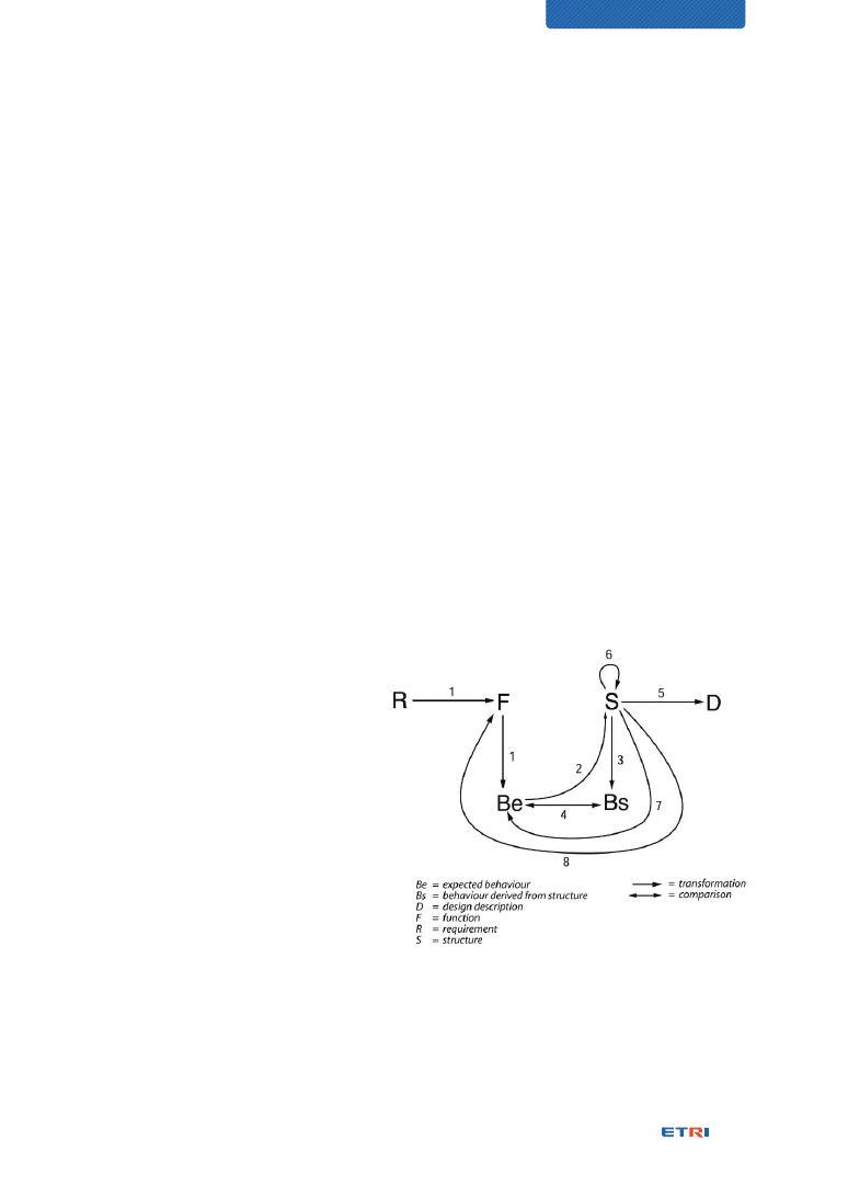
first, and then modeling of structure and behavior shall be followed. The FBS
(Function-Behavior-Structure) framework is a modeling methodology to deal with
the guideline, and there are other specific modeling and simulation guidelines.
Digital Twin modeling dimensions
A physical entity’s behaviors may be identified by various perspectives, such as
time, cost, performance, sustainability, and safety. What perspective is selected
depends on goals and purposes. We identified at least four modeling perspectives
for the Digital Twin, called modeling dimensions in this Technical Report, should be
considered and applied to detailed modeling. Other dimensions can be possible for
the Digital Twin as the BIM modeling dimensions have been expanded so far.
CHARACTERIZATION OF
DIGITAL TWIN

20
3D: This is an essential and definite dimension because physical entities shall be
formed in 3D as their Digital Twin models. If a complex physical system is to
be modeled to a corresponding Digital Twin system, some BIM dimensions
might be utilized. Since the measure of 3D dimensions representing point,
surface, shape, and space has already been maintained and well known, the
fidelity of 3D representations can be defined by the granularity of the shape,
surface, and space.
Time: This is another essential and definite dimension. Then the past and future
states can be distinguished, and the cause analysis by reproductive simulation
is possible by referring to the stored data. The measure of the time dimension
is also well known. The fidelity of time can be defined by the granularity of the
time span.
Roles: The role refers to the behavior of a physical entity that shall be performed.
The role can be presented as a set of behavioral functions that are coupled to
achieve the role. A physical entity may have multiple roles within a working
domain and different roles in a different working domain, represented as
different identities for the same physical entity. This feature is required to be
maintained separately by a modeling dimension. The measure of the roles
dimension and the resulting fidelity of roles cannot be defined. A role can be
specified in detail. The detailed roles had better be handled as specifically
divided roles, not by the fidelity perspective.
Properties: The property refers to a factor that affects a particular behavior of
a physical entity. The more properties of a physical entity are identified
and modeled, the more precisely the behaviors of its Digital Twin can be
conforming to those of the physical entity. Identifying the properties of a
physical entity is the act of finding the input parameters for its functional
behavior. The measure of the properties dimension depends on properties.
That is, a property can have its measure to describe the granularity of
distinction of the property. The fidelity of the properties dimension shall be
handled separately by the measure of each property.

21
Digital Twin federation
A specific problem in the real world doesn’t always happen due to a single cause,
but often various causes mixed one another. A complex system has suffered from
various problems through inter-related causes. For example, an environmental
concern may be challenged over multiple domains such as manufacturing factories,
transportation, energy production, and city. Thus, a single Digital Twin is required to
interact with other Digital Twin systems to handle cross-domain problems, resulting
in the federated Digital Twins.
Digital Twin interface
Michael Grieves pointed out that the data interface between Digital Twin and
Physical Twin is the last third element of a Digital Twin system. Without the data
interface, the interaction between them is impossible, and no intelligence can
be extracted. The digital thread is known as a technical solution. It is an interface
framework that may consist of a set of communication technologies to support
various communication requirements. But there is still a lack of information for the
digital thread.
Digital Twin awakening and Multi-persona Twin
The real world encompasses not only fixed physical entities but mobile physical
entities. While the same physical entity travels along its path, it may play different
roles at different places. Roles are established by purposes. In other words, a
purpose can define a set of roles.
It has been clarified that purposes define Digital Twin models, and different purposes
make different Digital Twins developed in having different behavior models.
The roles by different purposes can be characterized as individual identities that take
the roles, and the individual identities are presented as individual Digital Twins who
have represented from the same Digital Twin. They are called Multi-persona Twins.
CHARACTERIZATION OF
DIGITAL TWIN

22
The concept of Multi-persona Twins can raise a question, “how does a Digital
Twin finds and wear its Multi-persona Twin masks that fit the locations at different
places?”. In other words, the question is, “how can a Digital Twin recognize the right
roles it has to play at different places?”
There are two approaches, but combining them into one solution may be possible
by referring to the Bluetooth pairing technique. The first one is, all Multi-persona
Twins for a certain Digital Twin shall be pre-registered at their corresponding places
designated to play. When a physical entity comes in at a place, its designated Multi-
persona Twin for the place is activated, which is called Digital Twin awakening.
The other one is, the pre-registration is not assumed when a physical entity comes
in at a place, its Digital Twin shall discover possible Digital Twin domains of the place
and is plugged as a Multi-persona Twin in the Digital Twin domain selected for its
role play, which is called Digital Twin mobility.
Digital Twin characterization fidelity
The characterization fidelity refers to how much elaborately, specifically, and exactly
represented as many virtual models of its Digital Twin as possible for conforming
exactly to the real structure, behaviors, and personality of a physical entity. This is
analyzed by resolution perspectives of the characterization of the physical entity.
For example, the more characteristics of the Na’vi race are represented, the higher
fidelity of the avatar is made up.
The characterization fidelity may be presented as data parameters with processible
logic. Developing virtual models for representing a physical entity’s characteristics
is the act of formulating its behaviors, personality, and structure into machine-
processable forms, that is, data parameters and processing functions. Thus, the
higher fidelity a Digital Twin modeling is challenged in, the more data parameters
and functions the Digital Twin should handle, resulting in a more complex system.

23
Digital Twin visualization fidelity
Since the end-users of Digital Twin are people, how the Digital Twin looks to them is
a challenge to be pursued. The visualization fidelity refers to how much conforming
a Digital Twin (i.e., digital replica or avatar) looks like its physical entity closely. The
higher the resolution, the more visually the Digital Twin resembles the physical entity
in appearance.
There is a need for a fidelity measure that can be used to measure the conformity
of a Digital Twin (i.e., digital replica or avatar) to its physical entity. The fidelity can
be characterized by components. In terms of visualization, two fidelity measures for
resolution and latency that correspond to spatial and temporal measurements, re-
spectively, are provided.
The measure of space fidelity is defined by the resolution of space, i.e., the Dot Per
Inch (DPI). The measure of time fidelity is defined by the granularity of time span
through various latency time accumulated to the visualization latency time.
Digital Twin maturity model
The Digital Twin maturity model aims to provide an assessment tool for
understanding what Digital Twin levels are established and help develop a continuous
improvement plan towards higher levels. The proposed Digital Twin maturity model
is provided below.
Maturity
Level
Name
Functional requirements of elaboration
Examples
5
Autonomous
Digital Twins
Autonomous operations by live synchronization
and orchestration without any human intervention
N/A
4
Interactive
Digital Twins
Federated, synchronized, and interactive
operations among Digital Twins, but through
human intervention for action
Synchronization through an interface bus (e.g.,
Digital Thread) along with Physical Twin life-cycle
N/A
CHARACTERIZATION OF
DIGITAL TWIN

24
3
Dynamic
Digital Twin
Behaviors and dynamics modeled for operation
and simulation
What-if simulation provided
Cause analysis by reproductive simulation
Synchronization through a data link (e.g.,
MTConnect) during operation time
CAE, Digital
Factory,
Virtual
Singapore,
HILS, CPS,
etc.
2
Static Digital
Twin
Persistent, static, and initial data connection
No models of behaviors and dynamics but
process logics applied
Realtime monitoring
Partial automatic control, but mainly through
human intervention for action
SCADA,
DCS, CAM,
etc.
1
Look-alike
Digital Twin
Physical entity modeled to have a similar visual
appearance and rendered in 2D or 3D
CAD, etc.
Digital Twin and other relevant technologies
Cyber-Physical System (CPS): Comparison between Digital Twin and CPS is a hot
issue among R&D engineers and business stakeholders. It has been said that
Digital Twin is an implementation case of CPS; it is an enabling technology
for CPS; it is the core technology of CPS; and vice versa; or, even both are
the same. We are claiming that both Digital Twin and CPS are the same
thing from technical perspectives. But, we predict the Digital Twin can have
more improvement and business opportunities in the future according to our
analysis results by market acceptance and intuitive understanding view.
Virtual Reality (VR): While the peer relationship of Digital Twin is made with its
physical entity called Physical Twin, that of the Virtual Reality is made with a
human user, not its physical entity. One of the development tasks for Digital
Twin is how much closer a Digital Twin has to conform to its physical entity,
which is to develop a mirror-image twin. Virtual Reality considers tweaking
more significantly than mirror-image twinning. That is, Virtual Reality is likely
not that complementary to Digital Twin.

Flight simulator: While the peer relationship of Digital Twin is made with its physical
entity called Physical Twin, that of the flight simulator is made with a human
pilot, not its physical entity.
Augmented Reality (AR): It can enable overlaying of physical space with
virtual space for Digital Twin to work in both spaces simultaneously.
The peer relationship of Digital Twin is made still with its physical
entity, and human operators can intervene at the overlaid spaces in the
middle of the peer relationship, resulting in the Human-in-the-Loop
configuration. Augmented Reality is complementary to Digital Twin.
NOTE: Strictly speaking, the loop of the Human-in-the-Loop between two
peers is technically called a loopback interface. So, it can be called the Human-
in-the-Loopback system.
Mixed Reality (MR): It can enable human operators not to intervene between Digital
Twin and its physical entity but to interact with Digital Twin and physical entity
respectively, resulting in the circular system of Physical Twin, Digital Twin, and
people. The circular system can be called the Human-in-the-circular-Loop
system. Thus, Mixed Reality is not complementary to Digital Twin, but it is part
of Digital Twin and vice versa.


27
CHARACTERIZATION OF
DIGITAL TWIN
1. Why Beauty is Truth – a history of symmetry
2. Era of Digital Twin
3. Ego of Digital Twin
4. Technical insights from James Cameron’s Avatar
5. Characterization dimensions of Digital Twin
6. Digital Twin modeling
7. Digital Twin modeling dimensions
8. Digital Twin federation
9. Digital Twin interface – The Third Element
10. Digital Twin awakening by physical mobility
11. Digital Twin characterization fidelity
12. Digital Twin visualization fidelity
13. Digital Twin maturity model
14. Digital Twin and other relevant technologies
28
32
33
35
39
48
53
56
59
62
70
72
79
90
28
Why Beauty is Truth – a history of symmetry
1
1. Why Beauty is Truth – a history of symmetry
The heading is the title of a book authored by Dr. Ian Stewart, a mathematician who
explains various mathematical theories to deal with the concept of symmetry. The book
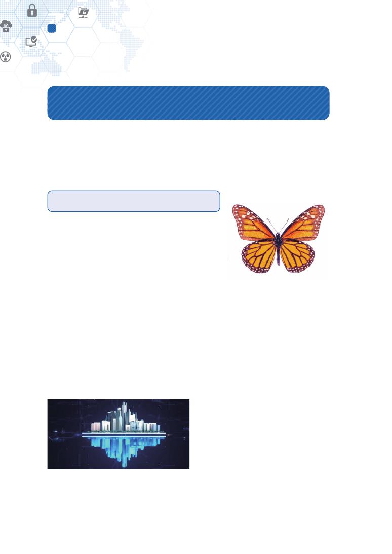
cover contains a butterfly like Figure 1. Wikipedia describes the symmetry as referring to
a sense of harmonious and beautiful proportion and balance [1].
The butterfly is in a typical shape of symmetry.
When humans recognize objects, they use pattern
matching in their memories to find similar ones
because it is more comfortable and less complicated.
So, people try to find symmetrical shapes and feel
satisfied with symmetrical patterns. They also feel
beautiful.
When we have to deal with a physical object, we
expect to deal with a symmetrical shape similar to
that object because we can intuitively understand the
object and feel how to manage it, suggesting exactly
the need for a twin system.
1.1. Digital Twin (DTw)
Figure 2 – Shape of a Digital Twin city
Rather than reinventing the definition of
the Digital Twin, we would like to provide
two existing definitions.
Wikipedia reads, “Digital twin refers to
a digital replica of potential and actual
physical assets (physical twin), processes,
people, places, systems and devices that
can be used for various purposes [2].”
Source: GettyImagesBank. You may
not distribute or resell the content
without permission.
Figure 1 – Symbol of
“Why Beauty is Truth”

29
CHARACTERIZATION OF DIGITAL TWIN
ISO 23247-1, “Automation systems and integration – Digital Twin framework for
manufacturing – Part 1: Overview and general principles” defines the Digital Twin for
manufacturing business fields as “manufacturing fit for purpose digital representation of
an observable manufacturing element with a means to enable convergence between the
element and its digital representation at an appropriate rate of synchronization [3].”
The Digital Twin model was first introduced in 2002 as a concept for Product Lifecycle
Management (PLM) without giving the model a name. Dr. Michael Grieves recently
discovered his presentation at a Society of Manufacturing Engineering (SME) Management
Forum, October 2002, which had the model. The model was soon named, but the name
has changed over time. It was originally named the Mirrored Spaces Model (MSM) but
later changed to the Information Mirroring Model. The model was finally referred to as
the Digital Twin, the name John Vickers of NASA had coined for the model. While the
name has changed over time, the concept and model has remained the same. In 2010,
NASA used Digital Twin in the space exploration technology roadmap and technology
development, and the basic concept was introduced and spread as a space exploration
system [4][5][6].
1.2. Cyber-Physical System (CPS)
A controversial issue for Cyber-Physical System and Digital Twin is a comparison
between them. Are they identical just with different names, or different from technical
and application perspectives? The answer from our analysis results is that they are
conceptually identical, their enabling technologies also are identical, but only different
stakeholders and different applications have been observed in their business domains,
respectively. We have analyzed them from engineering, market acceptance, and intuition
perspectives. Our conclusion is the Digital Twin can get more improvement and business
opportunities rather than CPS. Specific views are described below in “Cyber-Physical
System (p. 90)” of the clause of “Digital Twin and other relevant technologies.”
30
Why Beauty is Truth – a history of symmetry
1
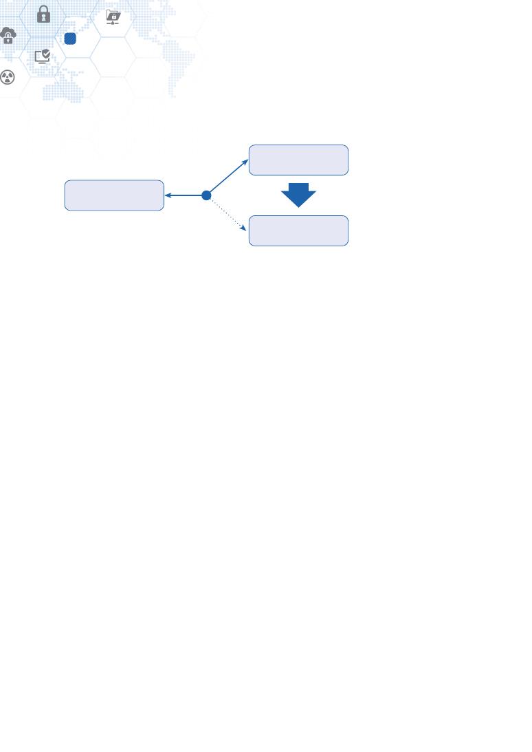
1.3. Hardware-in-the-Loop Simulation (HILS)
Control system
Virtualized exactly by
Function (purpose)
Control system
Control system
Figure 3 – Relational view of HILS-related systems [7]
Even though the Hardware-in-the-Loop has been used for usually testing hardware
systems such as controllers, cars, and turbines, its basic concept is the same with CPS
and Digital Twin. A HIL simulation system shall contain digital and/or mathematical
representations of all related dynamic systems for a target physical system, resulting in
a digital replica. As shown in Figure 3, part of or the whole plant system features and
dynamics are replicated virtually to the HIL simulator according to intended purposes.
From this matter, HILS, CPS, and Digital Twin have a similarity. The purpose of the control
system of Figure 3 is similar to why human intervention is necessary for the Human-in-
the-Loop configuration in Figure 31. Although the HILS systems are tailored for testing
purposes on specific targets in the market, it cannot be said that innovative entrepreneurs
will not evolve the HILS system into a kind of Digital Twin system.
NOTE: Figure 4 [7] of the paper shows an illustrative description of connecting a control
system with a simulated plant.
1.4. Short conclusion for the branding and technology names
Although CPS, Digital Twin, and HILS have the same basic concept, different business
stakeholders have developed and formed them within their business domains. For
example, CPS has been led by embedded system business stakeholders, Digital Twin has
been led by manufacturing stakeholders, and HILS has been by testing service providers.
There are two reasons behind the recent introduction and more spread of Digital Twins in
various fields. The first one is that the base technologies have been accumulated to the
extent that the Digital Twin concept can be specified and applied in new areas. Example
technologies are:

31
CHARACTERIZATION OF DIGITAL TWIN
⊙ Making a 3D model of a physical entity created as its Digital Twin model;
⊙ Visualizing the model through Augmented Reality, Virtual Reality technologies, etc.;
⊙ Developing virtual dynamics models of functions and operations of the object;
⊙ Collecting data while the actual operations of the object are monitored in real-time;
⊙ Analyzing data through big data, artificial intelligence, etc.;
⊙ Simulating future situations of the object through its virtual model and analysis
data; and
⊙ Reproducing the past state with accumulated history data.
The second reason is included in the intuition aspect of “Cyber-Physical System (p. 90).”
The intuition aspect refers to “The fast market penetration and current popularity of Digital
Twin can be said to be thanks to an intuitive name that anyone can quickly understand.
For an unfamiliar concept to survive and spread in the business ecosystem, a virtuous
cycle of acceptance and investment induces must be created. The Digital Twin can be
easily understood by anyone, including investors from even humanities background, and
mirror-image twins inspire people to trigger more diverse use cases. On the other hand,
the Cyber-Physical System has a barrier to its name so that capital investors, purchasing
decision-makers, and others may need a considerable amount of time to understand
it, compared to those with an engineering background.” CPS and HILS are engineering
names. An intuitive name can help penetrate the market more quickly.
NOTE: It should be noted that a “twin” consists of 2 people. Although called twin elder brother
or twin younger brother, a twin is a combination of two people. This mirror image of a twin
can make people and stakeholders including investors, feel friendly for the term.

32
Era of Digital Twin
2
2. Era of Digital Twin
As stated earlier, the concept of Digital Twin had arisen from the manufacturing area;
however, these days, it has been widely spread all over the areas it can reach, such as
cities, health, energy, airport, transportation, logistics, and agriculture.
At the time of the Internet of Things, it is easy to tempt end-users by labeling “Internet of
Things-ready” on every service and product. Lighting, air-conditioner, heater, air cleaner,
refrigerator, and even water purifier at home are connected to the Internet for ease of use.
In general, people tend to get inspiration by its name, not by its detailed technical features.
People have shown the same tendency to buy “Internet of Things-ready” products or
services.
The Digital Twin naturally embracing the Internet of Things is very easily understood and
gives deep inspiration to people from cutting-edge technology developers to policymakers.
It is just the beginning of the era of Digital Twin combined with Augmented Reality, Mixed
Reality, Cloud computing, Big data, Artificial Intelligence, and the Internet of Things, for
example.
33
CHARACTERIZATION OF DIGITAL TWIN
3. Ego of Digital Twin
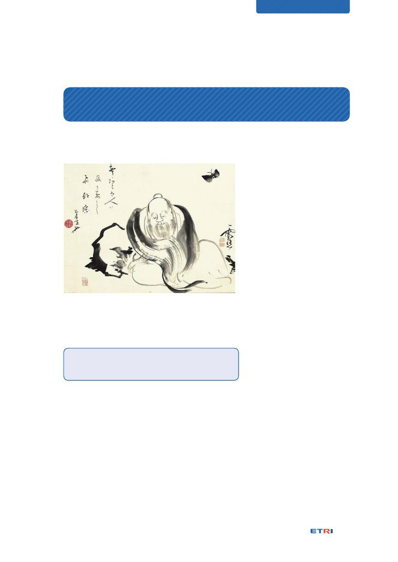
One of Zhuangzi’s most famous passages, an ancient Chinese philosopher, is the butterfly
dream – “Zhuang Zhou Dreams of Being a Butterfly.”
Figure 4 – Zhuangzi dreaming of a butterfly, by an 18th
century Japanese painter, Ike no Taiga [9]
“One night, Zhuangzi dreamed of
being a butterfly — a happy
butterfly, showing off and doing
as he pleased, unaware of being
Zhuangzi. Suddenly, he awoke,
drowsily, Zhuangzi again. And he
could not tell whether it was
Zhuangzi who had dreamt the
butterfly or the butterfly dreaming
Zhuangzi. But there must be
some difference between them!
This is called the ‘transformation
of things’ [8].”
The butterfly dream gives the
following insights for the ego of Digital Twin:
Am I dreaming of Zhuangzi or butterfly?
Who am I?
Transformation of things
Anything can be digitally transformed from the physical world to the virtual world.
It means that in the Digital Twin concept, one physical entity has a Digital Twin;
Continuous mutual influence
Anything in the world both physical and virtual, is keeping influence with each
other. This means the physical entity and its Digital Twin influence mutually, which
was also characterized as “twinning” [10];

34
Ego of Digital Twin
3
Multi-persona
According to the story above, I can be either myself or a butterfly, vice versa, the
butterfly can be a butterfly or myself. In the Digital Twin concept, a single physical
entity can be multiple single twins. For example, I can be either a Daddy Twin in my
Home Twin system, a Research Staff Twin in my Office Twin system, or a Patient
Twin in a Health Twin system. They are all my Digital Twins that have different roles
of myself, and they may be keeping mutual influence with each other. A single
physical entity, literally a single thing, may be digitally transformed multiply based
on its purposes; therefore, a single physical entity may have multiple Digital Twins
exposing different roles to the virtual world.
Ego of Digital Twin
The Digital Twin is myself just in a different form.
The Digital Twin is myself
just in a different form.
35
CHARACTERIZATION OF DIGITAL TWIN
4. Technical insights from James Cameron’s Avatar
The world-wide famous Avatar movie of James Cameron provides some technical insights
to characterize the Digital Twin concept. The avatar represents almost identically the Na’vi,
pronounced exactly the same as the Korean word for butterfly. We have exploited the
following insights from Digital Twin perspectives:
4.1. Model of Na’vi
A representation model depends on its purpose.
One purpose can develop a simple representation
model, and multiple purposes have to develop a
more complex type. The differences between
the avatars and Na’vi reflect this insight [11]. We
identified that the reasons why a Digital Twin
model has to be developed shall be tackled first.
NOTE: Example differences are: (a) Avatars retain the human configuration of five digits
on each hand and foot, as different from the native Na'vi who possess four digits on each
limb. (b) The Na'vi nose is flat and cat-like, while an avatar's nose has a more human-like
central ridge, in some cases quite pronounced [11].
4.2. Hometree (i.e., Kelutral) of Na’vi
“One of Na’vi clans on Pandora, Omaticaya, lives in an ancient tree called “Hometree”
about 150m tall. The tree is honeycombed with natural hollows and alcoves in which the
Na'vi sleep, eat, weave, dance, and celebrate their connection to Eywa. The hometree
has a hollow base supported by mangrove-like roots. Within this base, there are many
columns, creating a large central area. In this central area, the tree branches and limbs
form a natural spiral staircase, which the Na'vi use to move up and down the tree. The
hometree comprises a grove of intertwined trees of the same species that have grown
together, providing for mutual strength and structural reinforcement [12].” It can be noted
that the spiral roots of the hometree have made itself stabler, stronger, and more resilient,
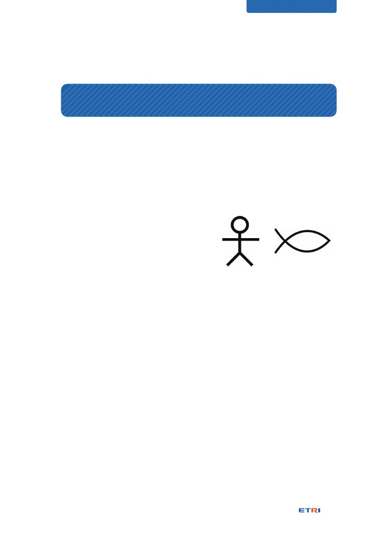
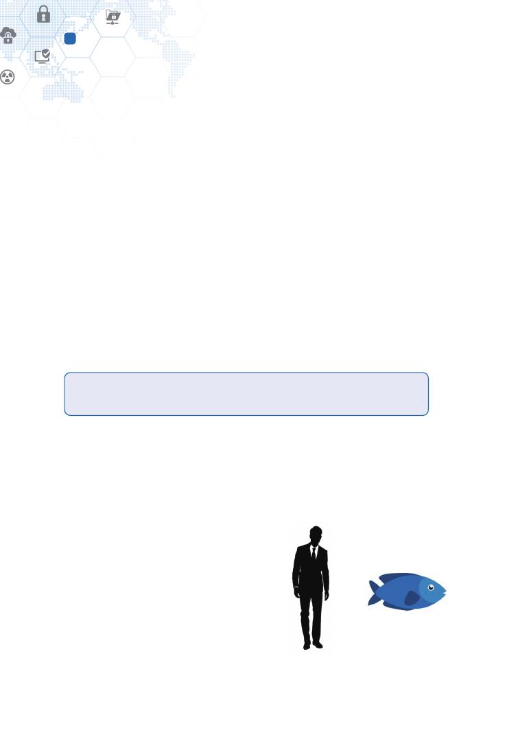
Figure 5 – Identification of human and fish
36
Technical insights from James Cameron’s Avatar
4
and they are the core parts of the tree. We identified that the Digital Twin requires some
core elaboration views to be constructed in a well-featured form. We call the analysis and
elaboration views as the modeling dimensions.
4.3. Avatar to Na’vi
The avatar is a genetically engineered body, a Human/Na’vi hybrid, meant to house a
human mind [11]. The avatar has many identical characteristics of the Na’vi race and
enough human neurophysiology for interactions between itself and its controller.
Each characteristic reflects the fidelity of the avatar from the resolution perspective of
characteristics of the Na’vi race. The more characteristics of the Na’vi race are represented,
the higher fidelity of the avatar is made up, conforming precisely to the Na’vi race. We
identified that how much specifically and exactly a Digital Twin model has to be developed
shall be defined, and call this matter as the characterization fidelity from the resolution
perspective of characterization.
The ego of a Digital Twin may wish to be its substance. Finally,
the avatar became Jake Sully with opening its eyes.
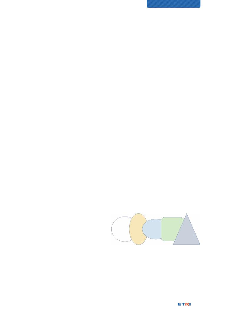
4.4. Visualization of Na’vi
Representation models for certain purposes may appear in different levels of visualization.
The human and fish in Figure 5 is the simplest way of appearance, having no skin.
Figure 6 shows a more specific appearance for the same representation model of which
purposes are to identify which one is human or
fish and how they are in shape. The visualization
is concerned because the end-users of the
Digital Twin are human beings who perceive on-
going situations from visual presentations. We
identified that how much specifically and exactly
a Digital Twin model has to appear conforming
exactly to its physical entity shall be defined, and
call this matter as the visualization fidelity from
the resolution perspective of visualization.
Figure 6 – Visualization of human and fish
37
CHARACTERIZATION OF DIGITAL TWIN
4.5. All linking of creatures to Eywa
“Eywa is the guiding force and deity of Pandora and the Na'vi. The Na'vi believe that
Eywa acts to keep the ecosystem of Pandora in perfect equilibrium. It is sometimes
theorized by human scientists that all living things on Pandora connect to Eywa through
a system of neuro-conductive antennae; this often explains why Na'vi can mount their
direhorse or mountain banshee steeds and ride them immediately without going through
the necessary steps required to domesticate such wild animals [13].” All the entities and
their representation models affect each other via their interactions. We identified that all
or part of Digital Twin models should interact together, and call this matter the federation
of Digital Twins.
4.6. Pandora Neural Network
All living organisms of Pandora – both flora and fauna – are connected by a neural network.
Animals and the Na’vi can access this network by using their neural queues [14]. On the
Na'vi, the neural queue is similar in appearance to long braided human hair that works as a
neuro-conductive antenna. But it is, in fact, an extension of the nervous system [15]. The
neuro-conductive antennae can establish the all linking, which correspond to Digital Twin
interfaces for all linking of Digital Twins.
4.7. Multi-roles by mounting and neural connection
A Na’vi can mount different species
and connect them through a system
of neuro-conductive antennae [13]. It
can control them without training for
handling, implying it can play multiple
roles naturally and adaptively according
to cooperation partners and situations.
We identified that a Digital Twin model
can play different roles at different places and have a different identity appropriately for a
particular living environment. We call this matter the Digital Twin awakening or mobility
with Multi-persona Twins.
Figure 7 – Me and Multi-persona
38
Technical insights from James Cameron’s Avatar
4
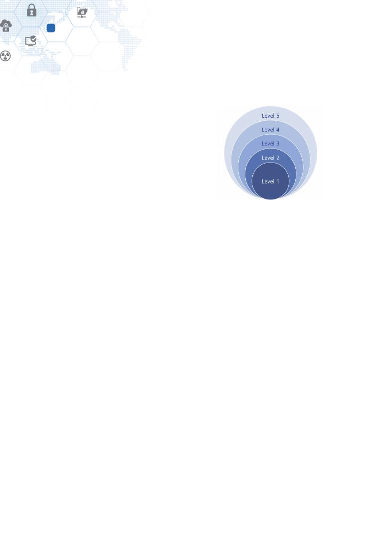
4.8. Equilibrium of Eywa
“Who's Eywa? Only their deity! Their goddess,
made up of all living things. Everything they
know! You'd know this if you had any training
whatsoever.” Norm Spellman explained Eywa
to Jake Sully [13]. It is believed that the Eywa
keeps the ecosystem of Pandora in perfect
equilibrium, which doesn’t mean equilibrium
is made everywhere, but maybe not at some
places and is made at the whole scale. We
identified that different levels of equilibrium may
be made at different locations, and Digital Twins
may be developed in different maturity levels.
We call this matter as the Digital Twin maturity.
Figure 8 – Layered model

39
CHARACTERIZATION OF DIGITAL TWIN
5. Characterization dimensions of Digital Twin
This clause deals with:
⊙ the summary of Digital Twin characteristics inspired by the Avatar;
⊙ some other Digital Twin characteristics identified by other study results; and
⊙ the comparisons among these study results.
Then, the remaining clauses explain each characterization dimension of Table 1 in detail
from technical perspectives.
5.1. Characterization dimensions captured from the Avatar
We have summarized the above technical insights and resulting Digital Twin characteristics
in a comparison table, Table 1.
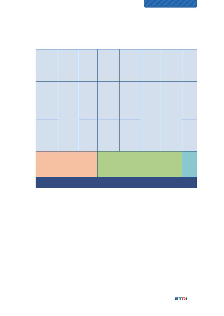
Table 1 – Comparison between Avatar and Digital Twin
Insights from James Cameron’s Avatar
Characterization dimensions of Digital Twin
Model of Na’vi
Digital Twin modeling
Hometree of Na’vi
Digital Twin modeling dimensions
Avatar to Na’vi
Digital Twin characterization fidelity
Visualization of Na’vi
Digital Twin visualization fidelity
All linking of creatures to Eywa
Digital Twin federation
Pandora Neural Network
Digital Twin interface
Natural multi-roles
Digital Twin awakening (via Multi-persona Twins)
Equilibrium levels of Eywa
Digital Twin maturity
Specific appropriate questions against the characterization dimensions can help analyze
the substance and characteristics of Digital Twin specifically. Table 2 provides the questions
from sensuous and engineering points of view.

40
Characterization dimensions of Digital Twin
5
Table 2 – Consideration points of characterization dimensions
Characterization
dimensions
Sensuous points
of consideration
Engineering points of consideration
Digital Twin
modeling
How is a physical
object represented
as a virtual model?
How is a physical object represented as virtual
behavior and structure models of its Digital Twin?
Digital Twin
modeling
dimensions
How many
perspectives can it
be analyzed by?
How many analysis perspectives can be applied to
an object for decomposing it and reconfiguring its
constituents in different forms?
Digital Twin
characterization
fidelity
How many similar
identities does it
have?
How many identities of a physical object are
represented as corresponding virtual models of
its Digital Twin for conforming as much exactly
as possible to its real structure, behavior, and
personality? This is analyzed by resolution
perspectives of the characterization of the reality.
Digital Twin
visualization
fidelity
How much does it
look like?
How much do a physical object and its Digital Twin
resemble each other in appearance? This is analyzed by
resolution perspectives of the visualization of the reality.
Digital Twin
federation
How does it
interact with
others?
How does a Digital Twin interact with other Digital
Twins for interactive cooperation? Their mutual
interactions are conceptualized as the Digital Twin
federation.
Digital Twin
interface
How does it
connect to others?
How does a Digital Twin exchange information with
other Digital Twins?
Digital Twin
awakening
(via Multi-persona
Twins)
How does it play
multi-roles?
How is a Digital Twin represented differently by roles
and responsibilities at different places? It can act as
a Multi-persona Twin at office, home, hospital, local
community, etc.
Digital Twin
maturity
How much
elaborately does it
interact?
How much profoundly do a physical object and its
Digital Twin bond each other for interaction? The
depth is represented as elaboration levels in terms
of maturity.

41
CHARACTERIZATION OF DIGITAL TWIN
5.2. Other Digital Twin characteristics by a research paper
A study paper, “Characterising the Digital Twin: A systematic literature review” authored
by David Jones and his four colleagues, has identified 19 characteristic themes shown in
Table 3 and core characteristics to the Digital Twin concept shown in Table 4 below [10]:
Table 3 – List of characteristic themes identified and their descriptions [10]
Themes
Description
1. Physical entity
A ‘real-world’ artefact, e.g., a vehicle, component, product,
system, model.
2. Virtual entity
A computer-generated representation of the physical artefact,
e.g., a vehicle, component, product, system, model.
3. Physical environment
The measurable ‘real-world’ environment within which the
physical entity exists.
4. Virtual environment
Any number of virtual ‘worlds’ or simulations that replicate the
state of the physical environment and designed for specific use-
case(s), e.g., health monitoring, production schedule optimization.
5. Fidelity
The number of parameters transferred between the physical
and virtual entities, their accuracy, and their level of abstraction.
Examples found in the literature include fully comprehensive,
ultra-realistic, high-fidelity, data from multiple sources, micro-
atomic level to the macro-geometrical level.
6. State
The current value of all parameters of either the physical or virtual
entity/environment.
7. Parameters
The types of data, information, and processes transferred
between entities, e.g., temperature, production scores,
processes.
8. Physical-to-virtual
connection
The connection from the physical to the virtual environment.
Comprises of physical metrology and virtual realization stages.
9. Virtual-to-physical
connection
The connection from the virtual to the physical environment.
Comprises of virtual metrology and physical realization stages.
10. Twinning and Twinning
rate
The act of synchronization between the two entities and the rate
with which synchronization occurs.
11. Physical processes
The physical purposes and process within which the physical
entity engages, e.g., a manufacturing production line.

42
Characterization dimensions of Digital Twin
5
12. Virtual processes
The computational techniques employed within the virtual world,
e.g., optimization, prediction, simulation, analysis, integrated
multi-physics, multi-scale, probabilistic simulation.
13. Perceived benefits
The envisaged advantages achieved in realizing the Digital Twin,
e.g., improved design, behavior, structure, manufacturability,
conformance, etc.
14. Digital Twin across the
Product Life-Cycle
The life-Cycle of the Digital Twin – (whole life cycle, evolving
digital profile, historical data)
15. Use-cases
The applications of the Digital Twin, e.g., reducing cost, improving
service, supporting decision making.
16. Technical
implementations
The technology used in realizing the Digital Twin, e.g., Internet-
of-Things.
17. Levels of fidelity
The number of parameters, their accuracy, and level of
abstraction that are transferred between the virtual and physical
twin/environment.
18. Data ownership
The legal ownership of the data stored within the Digital Twin.
19. Integration between
virtual entities
The methods required to enable communication between
different virtual entities.
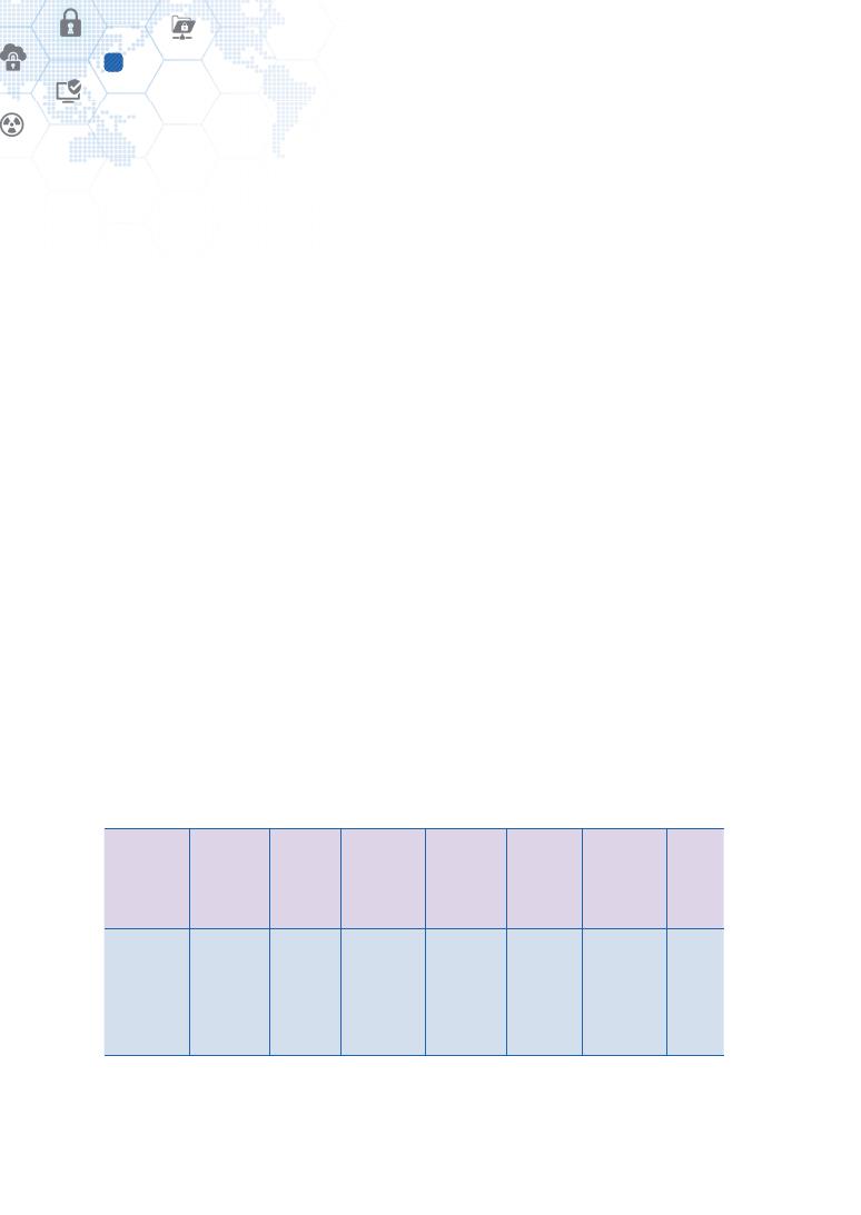
Table 4 – Core characteristics of the Digital Twin and their descriptions [10]
Characteristic
Description
Physical Entity/Twin
The physical entity/twin that exists in the physical environment
Virtual Entity/Twin
The virtual entity/twin that exists in the virtual environment
Physical Environment
The environment within which the physical entity/twin exists
Virtual Environment
The environment within which the virtual entity/twin exists
State
The measured values for all parameters corresponding to the
physical/virtual entity/twin and its environment
Metrology
The act of measuring the state of the physical/virtual entity/twin
Realization
The act of changing the state of the physical/virtual entity/twin
Twinning
The act of synchronizing the states of the physical and virtual
entity/twin
Twinning Rate
The rate at which twinning occurs

43
CHARACTERIZATION OF DIGITAL TWIN
Physical-to-Virtual
Connection/Twinning
The data connections/process of measuring the state of the
physical entity/twin/environment and realizing that state in the
virtual entity/twin/environment
Virtual-to-Physical
Connection/Twinning
The data connections/process of measuring the state of the
virtual entity/twin/environment and realizing that state in the
physical entity/twin/environment
Physical Processes
The processes within which the physical entity/twin is engaged,
and/or the processes acting with or upon the physical entity/twin
Virtual Processes
The processes within which the virtual entity/twin is engaged,
and/or the processes acting with or upon the virtual entity/twin
Since this Technical Report deals with the concept of Digital Twin inclusively of other
innovative views, the characteristic themes of Table 3 and Table 4 should be valid as
well in this document. There are two similar characterization points – levels of fidelity
and integration between virtual entities. But the others introduced in this document, i.e.,
modeling, modeling dimensions, visualization fidelity, data interface, Multi-persona, and
levels of maturity, are additional to those of David Jones’s study paper.
Levels of fidelity
“5. Fidelity” and “17. Levels of fidelity” are conceptually identical to the Digital Twin
characterization fidelity of Table 1. They are, however, not dealing with the visualization
fidelity.
Integration between virtual entities
Since the concept of Digital Twin was originated from the discussion about a
conceptual ideal for PLM (Product Lifecycle Management), there are some questions:
⊙ “how many Digital Twins exist?
⊙ Is one Digital Twin across the entire life-cycle appropriate?
⊙ Or, is a new one implemented at each phase of the entire life-cycle? [10]”
We had similar questions which, however, were not for the PLM aspect but the cross-
domain federation aspect. The difference between the two study results is the study of
David Jones deals with the integration of Digital Twins along the entire life-cycle of a
product. In contrast, our study deals with integrating Digital Twins across different business
44
Characterization dimensions of Digital Twin
5
domains, which may be interrelated, such as energy, transportation, environment, and
smart city domains. But both can share the same technology solutions with different data
parameters and attributes.
A linkage with Multi-persona Twin
The previous study paper hasn’t touched the Multi-persona Twin concept. But the
answers to the following questions may affect the formulation of the concept of Digital
Twin awakening or mobility by physical mobility:
⊙ “Once a product goes into production, do all Digital Twins have a single common
Digital Twin ancestor?
⊙ Or, is that ancestor cloned and duplicated across all instances?
⊙ If this is the case, then what is that Digital Twin ancestor: a finished design, or
some smaller subset of the finished design? [10]”
As described in “Integration between virtual entities” above, the analysis goals
are different, i.e., life-cycle management and multi-domain federation. But their
technical solutions might be similar or identical only with different data models.
5.3. Other Digital Twin characteristics by another research paper
Another study paper, “Digital Twin” authored by Rainer Stark and Thomas Damerau,
introduced the “Digital Twin 8-dimension model” for planning Digital Twins according to
purposes and business contexts, as shown in Figure 9 [16]:
1.
Integration
breadth
2.
Connectivity
mode
3.
Update
frequency
4.
CPS
intelligence
5.
Simulation
capabilities
6.
Digital
model
richness
7.
Human
interaction
8.
Product
life cycle
Level 0
Product /
Machine
Level 0
Uni-
directional
Level 0
Weekly
Level 0
Human
triggered
Level 0
Static
Level 0
Geometry,
kinematics
Level 0
Smart
devices (i.e.,
intelligent
mouse)
Level 0
Begin
of Life
(BoL)
45
CHARACTERIZATION OF DIGITAL TWIN
Level 1
Near field /
Production
system
Level 1
Bi-
directional
Level 1
Daily
Level 1
Automated
Level 1
Dynamic
Level 1
Control
behavior
Level 1
Virtual Reality
/ Augmented
Reality
Level 1
Mid
of Life
(MoL) +
BoL
Level 2
Field /
Factory
environment
Level 2
Automatic,
i.e., directed
by context
Level 2
Hourly
Level 2
Partial
autonomous
(weak AI
supported)
Level 2
Ad-hoc
Level 2
Multi-
Physical
behavior
Level 2
Smart hybrid
(intelligent
multi-sense
coupling)
Level 2
End-
of-Life
(EoL) +
BoL +
MoL
Level 3
World (full
object
interaction)
Level 3
Immediate
real time
/ event
driven
Level 3
Autonomous
(full
cognitive-
acting)
Level 3
Look-ahead
prescriptive
Digital Twin environment
Digital Twin behavior and capability richness
Digital
Twin life
cycle
context
Living Digital Twin
Figure 9 – Digital Twin 8-dimension model [16]
The 8-dimension model aims at providing a structured approach for planning the scope
and type of Digital Twin because the Digital Twin concept can be applied in numerous
fields and for different purposes [16]. The model can guide people to develop appropriate
Digital Twin models through such a step-by-step analysis and design methodology.
It consists of two categories, “Digital Twin environment,” and “Digital Twin behavior and
capability richness,” that have four dimensions for each and eight dimensions in total.
The Digital Twin environment sets working boundaries and conditions for Digital Twin
models, and the behavior and capability richness specifies a kind of fidelities of behavioral
dynamics of Digital Twin models. It can be said that they represent a horizontal analysis
view and vertical analysis view, respectively.

46
Characterization dimensions of Digital Twin
5
The Digital Twin 8-dimension model is defined as follows [16]:
⊙ Dimension 1, “integration breadth”: it describes the scope and extensions of the
Digital Twin and the environment to be considered within the Digital Twin;
⊙ Dimension 2, “connectivity mode”: it distinguishes the capabilities needed to realize
a Digital Twins’ communication capabilities;
⊙ Dimension 3, “update frequency”: it refers to the questions on how often a Digital
Twin needs to be updated with data from the digital shadow, i.e., data measured
and acquired during the operation and use of physical entities;
⊙ Dimension 4, “CPS intelligence”: it distinguishes different levels of intelligence
through, for examples, rule-based algorithms, machine learning, and artificial
intelligence;
⊙ Dimension 5, “simulation capabilities”: it distinguished the fidelity levels of simulation
by input parameters, time dependency, behavior, and prediction aspects;
⊙ Dimension 6, “digital model richness”: it describes which characteristics of a
product are mapped to its Digital Twin;
⊙ Dimension 7, “human interaction”: it refers to Digital Twin user interfaces; and,
⊙ Dimension 8, “product life cycle”: it is related to the product or system’s life cycle
phases in question supported by the Digital Twin.
These eight dimensions can be reached easily to a consensus as elaboration aspects for
Digital Twin designs and developments. We have done similar works in this document,
but from some additional and different views, which can complement each other.

47
CHARACTERIZATION OF DIGITAL TWIN
Table 5 – Comparison between two characterization models
Characterization dimensions by this
document
8-dimension model
Digital Twin modeling
Dimension 5, “simulation capabilities”
Dimension 6, “digital model richness”
Digital Twin modeling dimensions
Digital Twin characterization fidelity
Dimension 4, “CPS intelligence”
Dimension 6, “digital model richness”
Digital Twin visualization fidelity
Dimension 7, “human interaction”
Digital Twin federation
Dimension 1, “integration breadth”
Dimension 8, “product life cycle”
Digital Twin interface
Dimension 2, “connectivity mode”
Digital Twin awakening
(via Multi-persona Twins)
-
Digital Twin maturity
Dimension 2, “connectivity mode”
Dimension 3, “update frequency”
Dimension 7, “human interaction”
NOTE 1: Dimension 2, “connectivity mode” is associated with the interface model of the
Digital Twin model of Michael Grieves. Concerning the interface model, the sub-clause,
“Digital Twin interface – The Third Element (p. 59),” has related study results.
NOTE 2: Dimension 3, “update frequency” is associated with the information of “twinning”
and “twinning rate” [10].
NOTE 3: Dimension 7, “human interaction” is associated with VR, AR, and MR technologies.
Their study results are here in “Virtual Reality (p. 94)”, “Augmented Reality (p. 96)”, and
“Mixed Reality (p. 100)”.
48
Digital Twin modeling
6
6. Digital Twin modeling
6.1. Purpose-oriented modeling
Modeling is the act of producing a sculptured form in 2D or 3D and representing, often
mathematically, a process or behavior of a system. How to formulate and represent an
object or a system depends on its objectives. In order words, modeling something is done
as much as it is needed. Here are the examples:
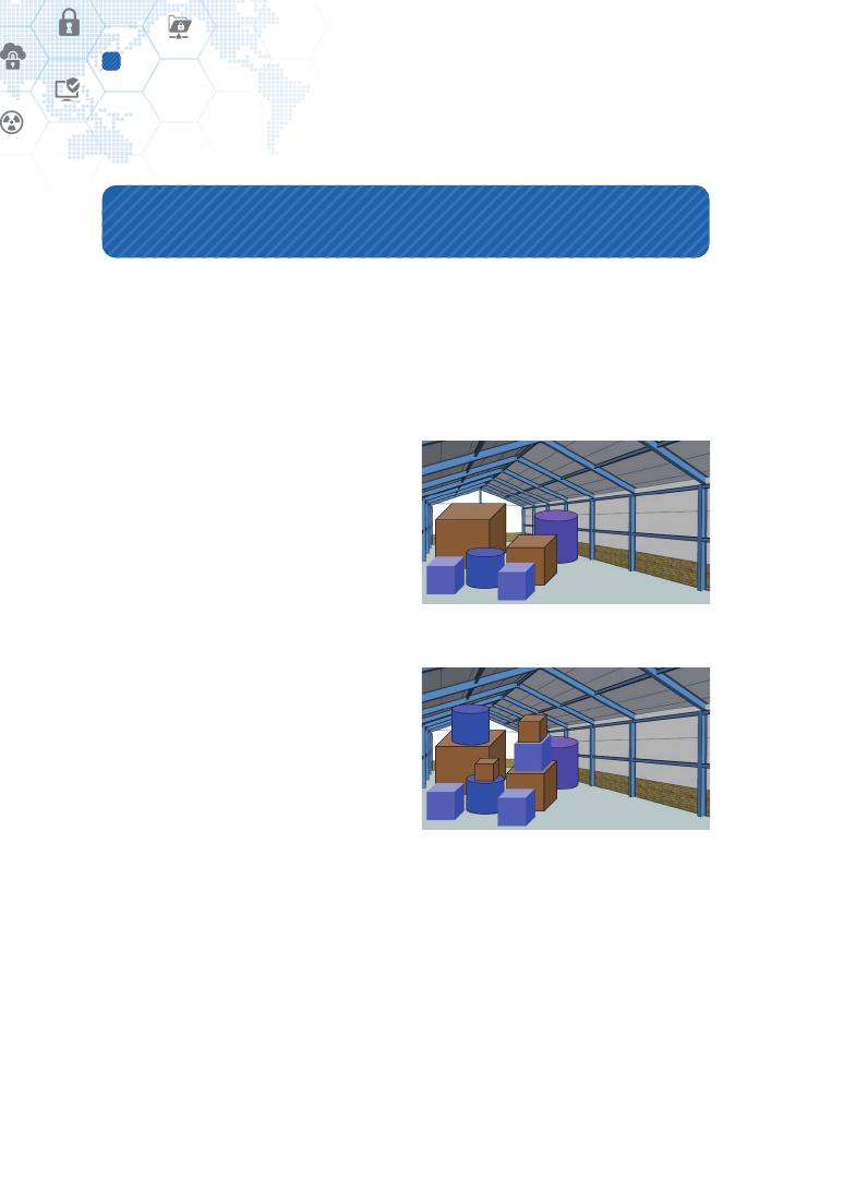
⊙ Case 1: Single-layer loading system
in a warehouse. At least three items
should be modeled:
• 3D rendering of the warehouse;
• 3D rendering of polygonal objects for
loading; and
• Optimum loading algorithm.
⊙ Case 2: Multilayer loading system in
a warehouse.Additionally, two factors
should be modeled:
• Weights of objects; and
• Material property of objects.
The loading algorithm of Case 1 doesn’t
have to consider the weights and material
properties of objects for loading. But that
of Case 2 shall consider them to avoid collapsing and getting broken.
Thus, representation models for the same objects are different and depend on their
purposes.
NOTE: The cost reduction has affected firmly setting up the purposes so far.
Figure 10 – Single-layer loading
Figure 11 – Multilayer loading

49
CHARACTERIZATION OF DIGITAL TWIN
For another example, modeling of human beings is a very complex work because they are
composed of a variety of many different characteristics as follows:
⊙ 3D shape model;
⊙ Behavioral models;
⊙ Skeletal structure models;
⊙ Muscular models;
⊙ Blood vessel models;
⊙ Personality models (e.g., Five-factor personality
models are extraversion, neuroticism, openness to
experience, agreeableness, and conscientiousness.
There is another well-known personality model, so-
called 16 MBTI (Myers–Briggs Type Indicator) types);
⊙ Physical constitution models (e.g., Tae-Yang type,
Tae-Eum type, So-Yang type, and So-Eum type by
the Sasang typology); etc.
6.2. Modeling methodologies
How to represent and formulate a physical entity or a system depends on its objectives.
Where a technical challenge is identified: how to develop a model or how to perform a
modeling process, i.e., modeling methodology. Its typical ways are well known to the
public:
1. Identify the problems to be solved.
⊙ It is the act of setting objectives for modeling and usages.
⊙ According to the problems identified and the objectives made, models to be made
may be different, and development methodologies also may be different, i.e.,
resulting in procedural steps, mathematical formulas, or others by the selected
methodologies.
Figure 12 – Human being

50
Digital Twin modeling
6
2. Formulate the problems.
⊙ The identified problems should be described specifically in technical forms as
pieces of representation works for modeling. For example, sensuous problems that
people may feel differently cannot be specified in technical forms and should be
taken out.
⊙ That is, formulating the problems is setting and describing all representation targets
for modeling.
3. Collect and process real system data.
⊙ The representation targets are modeled as virtual forms that perform behavioral
functions. The virtual forms shall resemble or be identical to real function elements.
It can be achieved by real system data reflecting inputs and outputs by behavioral
operations and dynamics.
⊙ Modeling pieces of representation reflects real system data into the virtual forms to
represent their realistic behaviors and dynamics.
4. Formulate and develop models.
⊙ This is the act of presenting the virtual forms
in a machine-readable syntax by which a
computer system can process and handle them
appropriately based on their functional logics of
behaviors and dynamics.
⊙ Formulating and developing virtual models
produces computer-processable function
elements that correspond to representation
pieces for solving the formulated problems.
⊙ Computer-processable forms may be presented in mathematical formulas,
procedural steps, selective options, algorithmic rules to be followed in calculations
or problem-solving operations, or other specific ways.
⊙ Through the above process of modeling a physical object, its resulting Digital Twin is
depicted, for example, in a logical and mathematical form for easier understanding
as shown in Figure 13. The factors, “a,” “b,” and “c” affecting the object in the real
f(a, b, c)
x
a
b
c
Figure 13 – Mathematical
illustration of a functional model
51
CHARACTERIZATION OF DIGITAL TWIN
world are given as input data into the Digital Twin model, “f(a, b, c),” and a reaction
of the object is simulated by “f(a, b, c),” and then the simulated reaction is produced
as output, “X.”
Additional steps for more elaboration of modeling are given below for information [17]:
Step 5. Validate the model.
Step 6. Document model for future use.
Step 7. Select an appropriate experimental design.
Step 8. Establish experimental conditions for runs.
Step 9. Perform simulation runs.
Step 10. Interpret and present results.
Step 11. Recommend a further course of action.
Tutorial explanations for them, including the earlier four steps, are found in a conference
paper, “Introduction to modeling and simulation,” by Anu Maria [17].
As illustrated in Figure 14 for its
process flow, the FBS (Function-
Behavior-Structure)
ontology
and framework can provide
another engineering guideline
for modeling. The Function (F) is
defined as the teleology (purpose)
of design objects; Behavior (B)
is defined as the attributes that
can be derived from the design
object’s structure; and, Structure
(S) is defined as the components
of the design object and their
relationships. The three ontological
categories are interconnected:
function is connected with behavior, and behavior is connected with structure. But there
is no connection between function and structure [18].
Figure 14 – The FBS framework process [19]

52
Digital Twin modeling
6
NOTE 1: In order words, the function corresponds to requirements made by purposes;
the structure corresponds to the parts figured statically; and, the behavior corresponds to
the way in which one acts or conducts oneself toward others and can be interpreted as
a role to play.
NOTE 2: In Figure 14, Behavior (B) is specialized into expected behavior (Be), i.e., “desired”
behavior, and behavior derived from structure (Bs), i.e., “actual” behavior. Requirements
(R) that represent intentions from the client that come from outside a model designer,
and description (D) that represents a depiction of the design created by the designer [19].

53
CHARACTERIZATION OF DIGITAL TWIN
7. Digital Twin modeling dimensions
Herein the dimension means an elaboration aspect that should take many efforts for
being achieved and be considered separately for easier progress from other analysis and
construction points. A reference case is BIM (Building Information Modeling) dimensions
to help design information models of various BIM use cases. The more the BIM market
has penetrated, the more it has brought dimensions as follows:
⊙ 3D (geographical structure, i.e., x-y-z)
⊙ Time-related aspects, such as scheduling, duration, etc.
⊙ Cost and budget aspects
⊙ Performance
⊙ Project life-cycle aspects
⊙ Sustainable, resilient, energy-efficient and environmental aspects
⊙ Facility management and maintenance aspects
⊙ Risk, safety, and health aspects
Wikipedia clarified that there is little consensus on definitions for the other dimensions
excepting for 3D and time aspects, and some organizations dismiss the terms [20].
The reason for this market situation is that there is no standard for handling the BIM
dimensions. But, in reality, BIM product providers adopted some of those dimensions for
their market competency. Customers can select an appropriate BIM solution according to
their application requirements.
Any analysis and development viewpoint can help a complex system decomposed, and
constituents reconfigured quickly and efficiently in different forms according to purposes
and requirements. This Technical Report provides the following Digital Twin modeling
dimensions to take advantage of the analysis and development viewpoint.

54
Digital Twin modeling dimensions
7
7.1. 3D
This is an essential and definite dimension because physical entities shall be formed in 3D
as their Digital Twin models.
A Digital Twin system can accommodate a simple physical entity or a complex system
that handles a set of problem domains. For example, a manufacturing factory or a city
area’s transportation management system can be represented as a Digital Twin system.
They may consist of a variety of many constituting physical entities that shall be modeled
in 3D. The BIM system might affect modeling of them, and some BIM dimensions may
be utilized in the Digital Twin system.
The measure of 3D dimensions representing point, surface, shape, and space has already
been maintained and well known in CAD, BIM, or other virtual model-related systems.
The fidelity of 3D can be defined by the granularity of the shape, surface, and space.
7.2. Time
Time is another essential and definite dimension. Then the past and future states can be
distinguished, and the cause analysis by reproductive simulation is possible.
All interactions between a physical entity and its Digital Twin are stored within the virtual
environment and made accessible to future virtual operations. This effectively means the
Digital Twin can learn from its past, both in actual historical performance and historical
virtual operations [10].
The measure of the time dimension is also well known. The fidelity of time can be defined
by the granularity of the time span.
7.3. Roles
In the concept of Digital Twin, this Technical Report defines the role refers to a behavior of
a physical entity that shall be performed. The role can be presented as a set of behavioral
functions that are coupled to achieve the role. Following the convention of Figure 13 (p.
50), “f(R)” is defined as a role to be carried out and a role can be composed of a set of
sub-roles, i.e., “f(R) = f(R1) + f(R2) + f(R3)”.

55
CHARACTERIZATION OF DIGITAL TWIN
According to the definition of the role above, the sub-role, “f(R1),” is a functional model
that shall perform a designated behavior by “f(X)” with the input variables, “a,” “b,” and
“c.” As a role or a sub-role can be composed of a set of behavioral functions, it can have
multiple functions, for example, “f(R1) = f(X) + f(Y) + f(Z)” where X, Y, and Z are designated
behaviors. Consequently, a role can be represented by a function of behavioral functions.
A physical entity may have multiple roles within a working domain and different roles in a
different working domain, represented as different identities for the same physical entity.
This feature is required to be maintained separately by a modeling dimension.
The measure of the roles dimension and the resulting fidelity of roles cannot be defined.
A role can be specified in detail. The detailed roles had better be handled as specifically
divided roles, not by the fidelity perspective.
7.4. Properties
In the concept of Digital Twin, this Technical Report defines the property refers to a factor
that affects a specific behavior of a physical entity. Referring to Figure 13, the function,
“f(X)” corresponds to the behavioral model of the physical entity and the input parameters,
“a,” “b,” and “c” correspond to the factors that affect the function, “f(X).” The more properties
of a physical entity are identified and modeled, the more precisely its Digital Twin behavior
can be conforming to that of the physical entity. Identifying the properties of a physical
entity is the act of finding the input parameters for its functional behavior.
The measure of the properties dimension depends on properties. That is, a property can
have its measure to describe the granularity of distinction of the property. The fidelity of
the properties dimension shall be handled separately by the measure of each property.
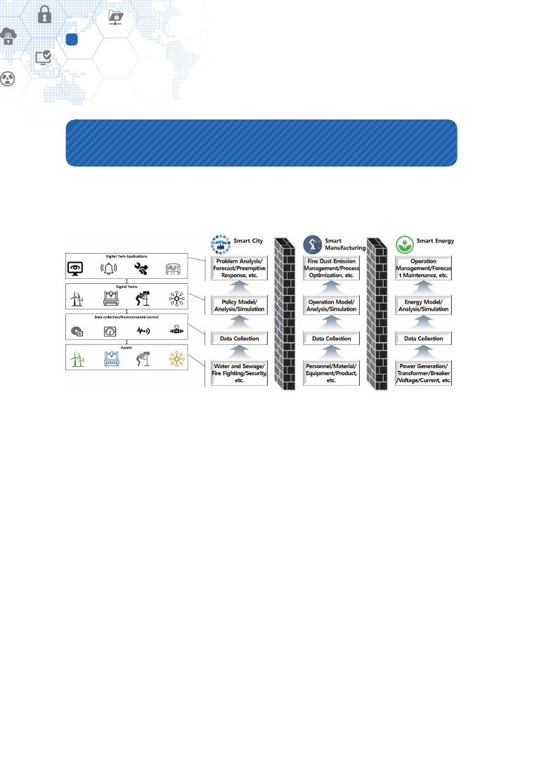
56
Digital Twin federation
8
8. Digital Twin federation
What always happens when a particular technology is used in multiple areas is a matter of
interworking. As Digital Twins are applied in more and more areas, more and more Digital
Twin interworking problems arise.
Figure 15 – Isolated Digital Twins
Figure 15 shows an overall structure of a Digital Twin system on its left side, and presents
Digital Twins deployed in smart city, smart manufacturing, and smart energy fields. It
depicts that Digital Twin systems operate only within their work domain but don’t interwork
with other Digital Twins. However, in city, factory, and energy areas, environmental
protection and energy-saving are prevalent issues across these domains.
A single domain Digital Twin system isolated from others has the following problems:
⊙ When a problem occurs due to multiple causes, it is difficult to identify the cause, and
there are limitations in response.
⊙ Integrated environment simulation and predictive maintenance across multiple
domains are not possible.
⊙ Multi-faceted decision making is difficult between different stakeholders.
57
CHARACTERIZATION OF DIGITAL TWIN
⊙ Co-relations and mutual side-effects occurring across multiple domains cannot be
identified.
⊙ No collaboration between stakeholders across the industrial ecosystem is possible.
The Digital Twin federation refers to a cooperation mechanism that supports interworking
between two or more individual Digital Twins in different domains and the same domain.
It could be a technical way to solve the problems listed above and extend smart services
across multiple domains. Figure 16 shows the functional interworking of a Digital Twin
system for federation with other Digital Twin systems.
Application
Simulation and Analysis
Modeling and Synchronization
Data collection and control
Figure 16 – Functional interworking for Digital Twin federation
Cities, factories, and power plants have the same concern about environmental problems
for reducing pollutants. Figure 17 presents an example of the Digital Twin federation to
mitigate the concern.
Figure 17 can be formulated, as shown in Figure 18, following the way of Figure 13 (p.
50). In Figure 18, an output of a particular function is an input to another function. The
interlacing of inputs and output to/from functions affected by each other can produce a
more exact answer.
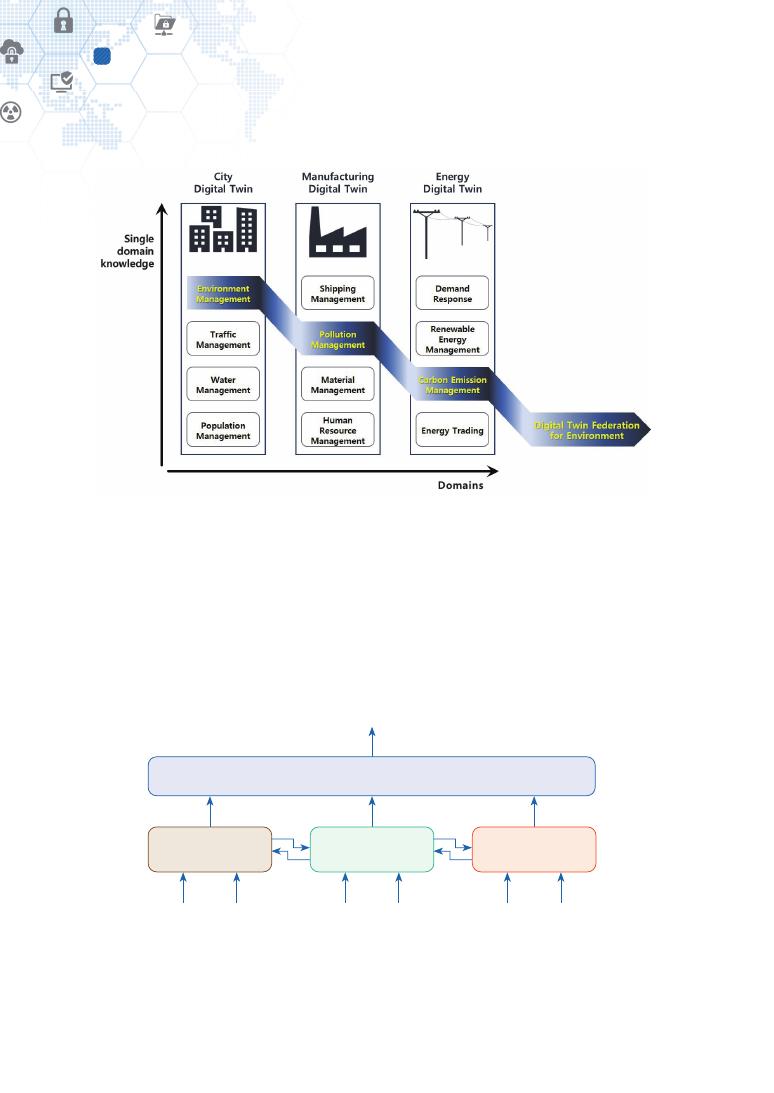
58
Digital Twin federation
8
Figure 17 – Digital Twin federation in city, manufacturing and energy for environment
Consequently, the Digital Twin federation aims at solving the problems that span multiple
domains where Digital Twin systems deploy.
Developing a federation between different Digital Twins systems is a technical challenge,
and various technologies may be introduced. The interoperability issue of various IoT
platforms is related to federation technologies. It is believed that the federation should be
set up at higher levels of interfaces, not low-level interfaces like data delivery interfaces.
f(X,Y,Z)
f(a,b,c)
f(d,e,f,g)
f(h,i,j)
X
a
e
i
b
f
j
Y
Z
K
Figure 18 – Mathematical illustration for Digital Twin federation
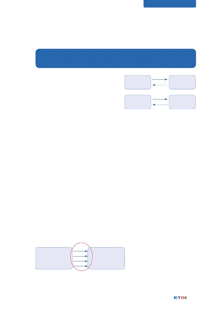
59
CHARACTERIZATION OF DIGITAL TWIN
9. Digital Twin interface – The Third Element
Michael Grieves drew the original concept
model of Digital Twin, as shown in Figure 19
(a). It contains three main parts: a) physical
products in Real Space, b) virtual products in
Virtual Space, and c) the connections of data
and information that tie the virtual and real
products together [21].
As shown in Figure 19 (b), the founder then
updated the concept model to adopt relevant evolutions since birth [6].
NOTE: Unfortunately, Figure 19 (b) confused an understanding of the concept and its
components. The concept name is Digital Twin, but a component name also is Digital
Twin. Thus, it has been misled occasionally that saying Digital Twin is indicating to the
Digital Twin component, not the whole concept. It should be noted that the Digital Twin
may be used as the representative name for the whole concept and also for the Digital
Twin component twinned from the Physical Twin. Even though there is an ambiguity, the
discussion context can tell which one is indicated.
It has been observed that data interfaces’ significance hasn’t been considered much
enough even though Michael Grieves addressed the data interface is one of the three key
elements for the Digital Twin.
Communication is a prerequisite condition for interactions between peer entities. Any
intelligence is not possible without communication within a group of entities. Data
communication takes place at every layer of the OSI 7 Layer model and does in cross-
layers as well. The communication works through an interface among communication
peers.
The interface is a very general term
and has been working at every place
for communication. This fact may
cause its value of existence, often
not invaluable, of which concern
Real space
Physical Twin
Virtual space
Digital Twin
Data
(a)
(b)
Data
Information
Process
Information
Process
Figure 19 – Concept models of Digital Twin
Physical Twin
{X = f(a, b, c, d, e)}
Digital Twin
{X1 = f(a, b, c)}
a
b
c
X1
The Interface
Figure 20 – More specified interface model
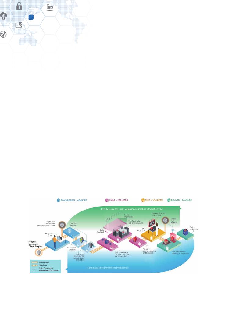
60
Digital Twin interface – The Third Element
9
was described at the NOTE of Level 4 of “Details of Digital Twin maturity levels (p.
84).” A particular type of interface should be considered very significant because it may
characterize different technology domains. How the interface has characterized various
technologies, such as VR, AR, MR, and flight simulation, against the Digital Twin, is
explained in “Digital Twin and other relevant technologies (p. 90).”
The interface view of Figure 19 (b) can be illustrated more specifically, as shown in Figure
20. The Physical Twin is represented mathematically as “X = f(a, b, c, d, e),” which means
five input variables affect the behaviors of the Physical Twin, and the resulting output by
internal behavior dynamics is produced as a reactive response, “X.” The Physical Twin may
be represented partially as a Digital Twin model, “X1”. This Digital Twin doesn’t represent
the whole characteristics of the Physical Twin but part of them by specific purposes
where a behavior model comprising input “a,” “b,” and “c” and output “X1” is represented
mathematically as the function, “X1 = f(a, b, c)”. This kind of input and output relationships
is called the interface.
The data interface model of Figure 19 and Figure 20 shows data exchanges only between
two peers of a twin. But it can extend its communication scope to other Digital Twins to
be incorporated with each other, and then the Digital Twin federation of Figure 18 can be
established. This kind of data interface path is a technical challenge to be tackled, and its
technical case has been branded as the digital thread, mainly in the US market.
Figure 21 – An illustration of the digital thread [34]

61
CHARACTERIZATION OF DIGITAL TWIN
The digital thread refers to the communication framework that allows a connected data
flow and an integrated view of the asset’s data throughout its lifecycle across traditionally
siloed functional perspectives. The digital thread concept raises the bar for delivering
“the right information to the right place at the right time” [22]. The experts of Deloitte
Consulting have captured this introduction into a flow diagram of data through the digital
thread, as shown in Figure 21.
Although the digital thread is a technical solution for the data interface, its technical details
haven’t been known much, and it looks like probably a proprietary solution. Or, it may be
just a concept like Digital Twin, and then, technology vendors may build their solution
packages to support the digital thread concept.
Although currently under development, there is another technical solution, IEEE 2888,
“Interfacing Cyber And Physical World Working Group,” that consists of one on-going
project, IEEE P2888.1, “Specification of Sensor Interface for Cyber and Physical World,” and
the other three planned projects, IEEE P2888.2, .3, and .4, respectively, “Specification of
Actuator Interface for Cyber and Physical World,” “Specification of Digital Synchronization
Framework between Cyber and Physical World,” and “Reference Architecture for Virtual
Reality Disaster Response Training System in Large Space.”
The interface relationships can identify how Digital Twin can be associated with VR, AR,
MR, and flight simulation in terms of similarity and difference. The clause, “Digital Twin
and other relevant technologies (p. 90),” contains relevant analysis results.

62
Digital Twin awakening by physical mobility
10
10. Digital Twin awakening by physical mobility
10.1. Physical mobility
While some manufacturing equipment in a factory is fixed, its production outputs, i.e.,
products, travel toward their customers. The real world has lots of mobile physical entities,
and they play specific roles assigned to themselves in designated locations. Here three
case scenarios are given for examples:
⊙ A product travels from its manufactured location along its entire life-cycle to the end-
of-life treatment;
⊙ A car leaves the garage, travels along the roads, and parks in a parking lot;
⊙ While people move in a day, they act as fathers or mothers at home, workers at
offices, patients at hospitals, guests at restaurants, and players at games.
Their activity in common is the mobility of physical entities, called physical mobility. What
should be done for Digital Twinning operation when a physical entity moves from one
place to another place? Where it should be noted that the Digital Twin plays different roles
with different responsibilities at different places.
10.2. Multi-persona Twins
Different roles can be interpreted as different
purposes. That is, the purpose defines the roles.
The FBS framework, as one of Digital Twin modeling
methodologies, specifies that purposes, behaviors, and structure should be analyzed first
to develop a corresponding Digital Twin for its physical entity. It means that different
Digital Twins by different purposes should be developed for different roles of a physical
entity at different places. That is, a physical entity should have different Digital Twins at
different places, which is characterized as a multi-persona and called Multi-persona Twin.
Here a clarification issue is identified: a single Digital Twin plays a single role only or multiple
roles by multi-purposes. To answer the question, this question of what distinguishes
between different Digital Twins should be answered first. The context-based distinction
The purpose defines the roles.

63
CHARACTERIZATION OF DIGITAL TWIN
could be one solution. All responsible roles of a physical entity can be grouped into a set of
role clusters by contexts of primary roles and responsibilities. That is, one context makes
one role cluster. The role clusters can correspond each to a Digital Twin while a Digital
Twin can play multiple roles.
A mathematical formula can represent these relations
for easier understanding. When “f(X) = f(Y) + f(Z)”
where “f(Y) = f(a, b, c)” and “f(Z) = f(a, d, e)”,
⊙ the factor, “a,” “b,” “c,” “d,” and “e” correspond to roles;
⊙ a context can set up a group of roles, and multiple contexts set up corresponding sets
of groups; in other words, multiple roles are classified in a set of groups by contexts;
Context makes a group.
Role or Purpose [23]
By Mike Staver
All of us have roles. We are leaders, agents, employees, parents, boyfriends, girlfriends,
husbands, wives, etc. We perform numerous tasks based on the roles we identify ourselves
in. While these roles are important and help us build our perception of ourselves and our lives,
I am wondering if there might be a deeper, more profound way to look at how we occupy
and manage our place in the world. While it is important to be clear about our role, roles are
really functions or positions we perform and hold. The more important place to focus is on our
purpose.
Roles become hollow places to occupy if we are not clear and in alignment with our purpose.
Your purpose is about your intent, your raison d’etre (reason for being) as the French say. As we
examine our roles, the real, underlying question is, why are we doing what we are doing? Why
are we fulfilling the roles we are in? Roles become empty and unfulfilling without the clear and
intentional understanding of why. Why are you a parent? Why are you a leader? Why are you
a boyfriend, girlfriend husband or wife? Why do you do the job you do? The answer to these
questions is what matters most.
Purpose is what keeps us going when we feel frustrated or annoyed in our role. Purpose is
the fuel that endures and overcomes the obstacles we face. Purpose is what helps us make
decisions about how we spend our time, the people we love, the jobs we do and the life we
lead. Many don’t think about purpose or why they do what they do. This month I encourage you
to consider your purpose. Here are the steps to get you started:
1. What is the reason you are fulfilling the roles you fulfill? (i.e., I am a coach and a speaker.
Those are roles. My purpose in those roles is to help people live better lives as they define
them. I could hold those roles without clear purpose but that would leave me hollow.)

64
Digital Twin awakening by physical mobility
10
⊙ each group is identified as a role cluster;
⊙ the group of “a,” “b,” and “c” is one role cluster and presented as “f(Y) = f(a, b, c)”;
⊙ the group of “a,” “d,” and “e” is the other role cluster and presented as “f(Z) = f(a, d, e)”;
⊙ the role clusters are represented each as a Digital Twin, resulting in a Multi-persona
Twin;
⊙ the sub-functions, “f(Y)” and “f(Z)” are represented each as a Multi-persona Twin;
and,
⊙ the physical entity has two Multi-persona Twins.
NOTE: This statement can be clarified by answering the following sub-clause,
“Mother and Multi-persona Twins vs. only Multi-persona Twins.”
Consequently, one Digital Twin can represent multiple purposes and behaviors for twinning
a physical entity and so Digital Twins can accommodate role clusters by each.
10.3. Mother and Multi-persona Twins vs. only Multi-persona Twins
Here two more discussion issues about a particular Digital Twin and equivalence are
identified.
⊙ “Is it required to have a particular mother Digital Twin and the other Multi-persona
Twins? Just in case, the mother Digital Twin can replicate all other Multi-persona Twins
by different roles. Here another question is, are they fairly equivalent even though they
are designated as mother Digital Twin and Multi-persona Twins differently?
2. Do your choices reflect your purpose? Living in alignment with your purpose requires
choices that support your purpose. Sometimes those are difficult to make.
3. Does your behavior reflect your purpose?
4. Are you willing to sacrifice certain elements of the roles you have to live, love and serve
in alignment with your purpose?
5. Do you find numerous ways to serve?

65
CHARACTERIZATION OF DIGITAL TWIN
⊙ Or, are there all engaged Digital Twins Multi-persona Twins with no particular mother
Digital Twin? Also, are they fairly equivalent from the identity perspective?
Fairly equivalent Multi-persona Twins mean all of them are fairly equal with no privileges
but with different roles and related capabilities.
The answers can affect how the Multi-persona Twin should be designed and processed
with appropriate data interfaces.
10.4. Digital Twin awakening or mobility
One key question is,
⊙ “How does a Digital Twin wear its Multi-persona Twin masks that fit the locations at
different places?
⊙ In other words, how can Digital Twins play the right roles at different places?”
This question is very similar to what David Jones’s research paper provided: “There are
also questions,
⊙ How many Digital Twins exist?
⊙ Is one Digital Twin across the entire life-cycle appropriate?
⊙ Or, is a new one implemented at each phase?
⊙ And either way, how are transitions between phases managed?
⊙ Once a product goes into production, do they all have a single common Digital Twin
ancestor?
⊙ Or, is that ancestor cloned and duplicated across all instances?
⊙ If this is the case, then what is that Digital Twin ancestor: a finished design, or some
smaller subset of the finished design?”
Here two approaches may be possible: Digital Twin awakening or mobility both triggered
by physical mobility.

66
Digital Twin awakening by physical mobility
10
Digital Twin awakening
All Multi-persona Twins for a certain Digital Twin shall be pre-registered at their
corresponding places where they are designated to play. When a physical entity
comes in at a place, its designated Multi-persona Twin for the place is activated. When
it comes out, the Multi-persona Twin is deactivated. This approach’s advantage is that
the problem domain can be pre-established, and its appropriate limitations can easily
control technical issues. The requirement of pre-registration may be a processing
burden, but it may be suitable for managing stability with minimizing uncertainty.
Digital Twin mobility
It is not assumed all Multi-persona Twins be pre-registered. Within its Digital Twins
territory, a management body cannot expect who will be enrolled and play assigned
roles in advance. When a physical entity comes in at a place, its Digital Twin shall
discover possible Digital Twin domains of the place and is plugged as a Multi-persona
Twin in the Digital Twin domain selected for its role play. This approach’s advantage
is that the pre-registration is not necessary, which might be beneficial if a city Digital
Twin domain has to cover nation-wide physical entities and when they come in and
who comes in are not deterministic.
Two sides of the same coin
Those two approaches may be two sides of the same coin. The Bluetooth pairing is
an example. A laptop doesn’t have to register every mouse device in advance; that is,
pairing profiles between them don’t have to be pre-established. When a new mouse
device is located near the laptop for connecting, the laptop does a discovery process
for any connecting device, and a pairing process proceeds between them. After a
pairing profile is established, the connection between both devices is automatically
made as a kind of activation process whenever they get close. The pairing process is
a pre-registration process for plugging into the laptop. This pairing operation scenario
can accommodate both scenarios of the Digital Twin awakening and mobility.
For another example, a mouse can play three different roles. Scrolling pages and
clicking points are a typical use-case. It can act as a scanner for producing images
and also as a game-playing device like a joystick. A super Digital Twin may handle
all of the roles, but three Multi-persona Twins can do them separately by each. An
architectural efficiency can make the decision.

67
CHARACTERIZATION OF DIGITAL TWIN
10.5. Multi-persona Twins having partially common or wholly different
roles?
Operation of Multi-persona Twins may meet another technical challenge: having partially
common roles or wholly different roles for all Multi-persona Twins. Figure 22 depicts
example scenarios for an ambulance car to clarify the situation.
⊙ A Digital Twin of the ambulance car (hereafter Ambulance Twin) may interact with a
Digital Twin of a parking lot management system (hereafter Parking Lot Twin). The
Parking Lot Twin can guide the Ambulance Twin to an appropriate parking lot space
to meet the parking limitations by physical size problems.
⊙ While the Ambulance Twin is taking an emergent patient to a hospital, it might have
to interact concurrently with different Digital Twin systems.
• It contributes to air pollution and is required to interact with an air pollution
management Digital Twin system.
• It contributes to a traffic jam on the roads to the hospital and is required to interact
with a load traffic management Digital Twin system to get feedback to help drive
fast to a nearby hospital.
• It may have to interact with the hospital’s emergency care Digital Twin system to
help first aid services.
• It may have to interact with a repair and maintenance Digital Twin system for the
ambulance car’s health management. When the ambulance gets in trouble while
moving to the hospital, emergent care for the ambulance car can safely travel to
the hospital.
⊙ An electric ambulance car can be charged and can serve as a supplier of stored
electricity to the power grid in an emergency to mitigate the peak demand of
power while it is parked. Where the Ambulance Twin has to interact with an energy
management Digital Twin.
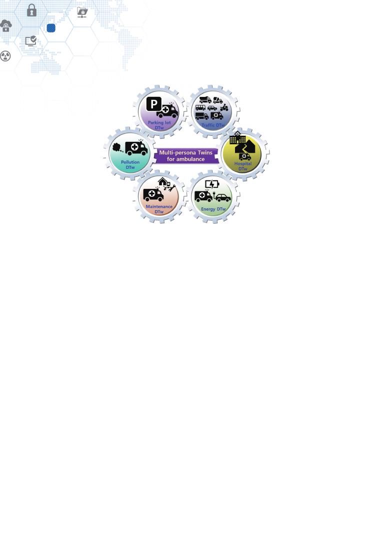
68
Digital Twin awakening by physical mobility
10
Figure 22 – Multi-persona Twins for ambulance
Every interaction relation with counterpart Digital Twin systems is associated with each
a role cluster, as mentioned above. The interaction shall be handled by a Multi-persona
Twin, which means the Ambulance Twin shall have multiple Multi-persona Twins for
interactions with corresponding counterpart Digital Twin systems. That is, six role clusters
and six corresponding Multi-persona Twins are engaged in the operation scenarios.
The ambulance Digital Twin shall wear its Multi-persona Twin masks accordingly to its
counterpart Digital Twin in domains or be a designated Multi-persona Twin of a physical
entity to its counterpart Digital Twin. The answer to the question can make the decision,
“Mother and Multi-persona Twins vs. only Multi-persona Twins (p. 64)”.
Table 6 provides three common roles, for example, across six work domains of the
Ambulance Twin.
⊙ Vehicle status: a vehicle has various vehicle status and operating parameters such
as the number of seats, fuel type, level of fuels, running speed, etc. Some of them
can help cooperation partners of each work domain learn the ambulance car’s current
status and do designated works related to the car.
⊙ Driver’s status and owned skills: a driver may have a physical disability that requires
special care, for example, at a parking lot. She or he may have technical skills for a
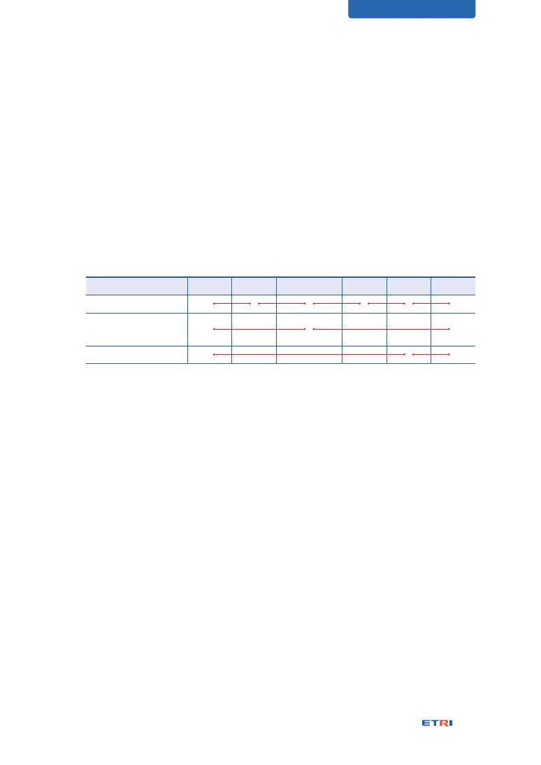
69
CHARACTERIZATION OF DIGITAL TWIN
particular repair and maintenance and can handle an emergent situation for the car.
A Traffic Twin may want to use the driver's status to predict sudden anomalies in
moving vehicles in controlling traffic flow.
⊙ First aid: a driver or a passenger may serve the first aid service. This information
might have to be shared with cooperation work domains, and emergent care can be
extended.
Table 6 – Identification of common roles across work process domains
Common role
Parking Pollution Maintenance
Energy
Hospital
Traffic
Vehicle status
●
●
●
●
●
●
Driver’s status and
owned skills
●
●
●
First aid
●
●
●
The ambulance vehicle’s physical operation status affects all the travel cases and should
do specific reactive actions against any operation problem. Thus, the ambulance car’s
monitoring and reactive controls can be classified as a common role.
It can be noted consequently that Multi-persona Twins may be composed of some
common roles and mostly different roles. The mathematical forms, “f(Y) = f(a, b, c)” and
“f(Z) = f(a, d, e),” in the sub-clause, “Multi-persona Twins (p. 62),” has depicted a common
factor, “a” shared by the function, “f(Y)” and “f(Z).”
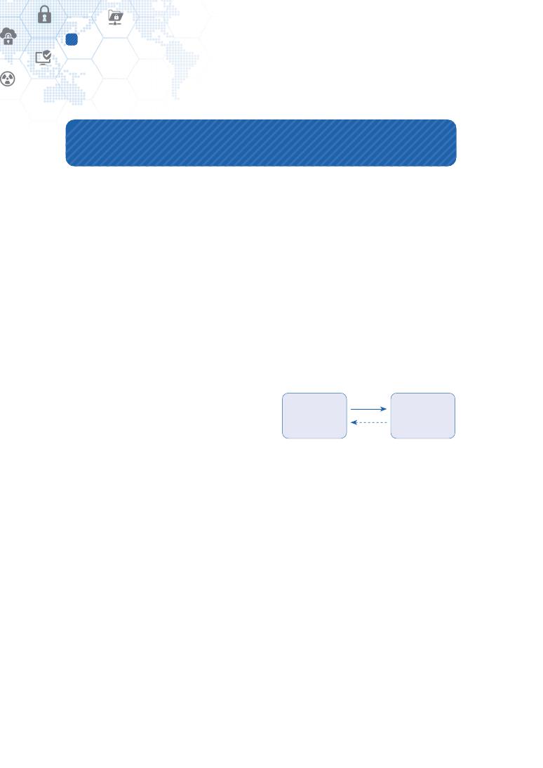
70
Digital Twin characterization fidelity
11
11. Digital Twin characterization fidelity
The characterization fidelity is described as how much elaborately, specifically, and exactly
represented as many virtual models of its Digital Twin as possible for conforming exactly
to the real structure, behaviors, and personality of a physical entity. In other words, it can
be questioned how many identities of a physical entity are represented as corresponding
virtual models of its Digital Twin. This is analyzed by resolution perspectives of the
characterization of the physical entity. Then, the more characteristics of the Na’vi race are
represented, the higher fidelity of the avatar is made up.
NOTE 1: The FBS framework specifies that modeling a physical entity is performed by
analyzing behaviors and structure according to purposes [19]. But the above description
includes the personality aspect additionally. The reason is to support the consideration of
human behaviors while participating in the Human-in-the-Loop situation enabled by the
Digital Twin with Augmented Reality and Mixed Reality technologies.
NOTE 2: The virtual models of a Digital Twin
may represent roles to play, behaviors,
structure, and personality of its physical entity.
NOTE 3: The personality can apply not only
to people but to other physical entities. The
physical entities’ personality may correspond to
specific properties that may affect the physical entities’ behaviors.
The initial concept for the fidelity has been already touched in terms of granularity by Dr.
Michael Grieves. Figure 23 shows his basic model for the Digital Twin, wholly consisting
of Physical Twin, Digital Twin, and the interface between them. He explained, “The Digital
Twin is the information construct of the Physical Twin. The key assumption is that the
type, granularity, and amount of information contained in the Digital Twin is driven by use
cases [6].” The granularity corresponds to the characterization fidelity for developing a
Digital Twin from its physical entity, i.e., Physical Twin.
David Jones’s research paper also picked up the fidelity as a challenge issue shown in
Table 3. It reads, “The higher the fidelity, the closer the virtual and physical twins are
aligned and, for example, the more accurate the simulation, modelling, and optimization
Physical Twin
Digital Twin
Figure 23 – Basic concept model for the
three key elements, Physical Twin, Digital
Twin and Interface
Data
Information

71
CHARACTERIZATION OF DIGITAL TWIN
will be [10].”
How much higher fidelity should be made depends on goals and purposes, as described
in “Digital Twin modeling (p. 48).” For example, how many diverse characteristics of a
human entity should be modeled is described together with Figure 12 (p. 49).
The characterization fidelity may be presented as data parameters with processible logic.
Developing virtual models for representing a physical entity’s characteristics is the act
of formulating its behaviors, personality, and structure into machine-processable forms,
i.e., data parameters and processing functions. Thus, the higher fidelity a Digital Twin
modeling is challenged in, the more data parameters and functions the Digital Twin should
handle, and the more complex system developed.
In other words, referring to “Digital Twin modeling dimensions (p. 53)”, their granularity
affects the fidelity of a physical entity’s characterization.
⊙ Fidelity depends on how many roles are defined. That is, “f(R) = f(R1) + f(R2) + f(R3)
+ …” where R is a role, and R1, R2, and R3 are its sub-roles.
⊙ Fidelity depends on how many behavioral functions are defined for a role. That is,
“f(R1) = f(X) + f(Y) + f(Z) + …” where X, Y, and Z are behaviors to be performed.
⊙ Fidelity depends on how many variables are defined for a behavioral function. That
is, “f(X) = f(a, b, c, …)” where a, b, and c are input data parameters to affect the
behavioral function.
⊙ Fidelity depends on the granularity of time as well.
The 3D dimension of “Digital Twin modeling dimensions (p. 53)” affects the Digital Twin
visualization fidelity.

72
Digital Twin visualization fidelity
12
12. Digital Twin visualization fidelity
Following the terminology conventions of ISO TR 24464, digital replicas can be made of
simple digital entities such as polygons or point clouds from the visualization perspective.
When fine details of a physical entity down to the nanoscale or molecular scale are required,
the corresponding digital replica is very challenging to be developed due to its complexity
and data volume. Even though nano-scale modeling is used on a molecular basis in the
computational chemistry, it is not usual in other areas. While modeling a physical entity, it
is necessary to simplify the entity to the extent necessary for its intended use.
There is a need for a fidelity measure that can be used to measure the conformity of a
digital replica to its physical entity. The fidelity can be characterized by components. In
terms of visualization, this Technical Report identifies two fidelity measures for resolution
and latency that correspond to spatial and temporal measurements, respectively.
12.1. Taxonomy of Digital Twin visualization
ISO TR 24464 defines a technical taxonomy for the Digital Twin, as shown in Figure 24,
and the items in blue indicate the visualization elements [24]. It categorizes the Digital
Twin concept into physical asset, avatar (digital replica), and interface, respectively, which,
in terms used by Michael Grieves, correspond to a physical rocket in the real space, a
digital rocket in the virtual space, and the data connection between them.
Regarding the visualization elements,
⊙ the physical asset itself has visibility and is sometimes presented through a GUI to
users, indicated as “Information to user” in Figure 24;
⊙ Sensor data is a bundle of data transmitted from the physical asset to an avatar (digital
replica). The physical asset’s operating data and its analyzed results in a graph or any
other form are elements of visualization. The resolution is an essential attribute in the
visualization process; and,
⊙ All of the avatar (digital replica) parts in Figure 24 belong to the visualization elements.
Since they all exist in digital digits, people cannot recognize them without visualization.
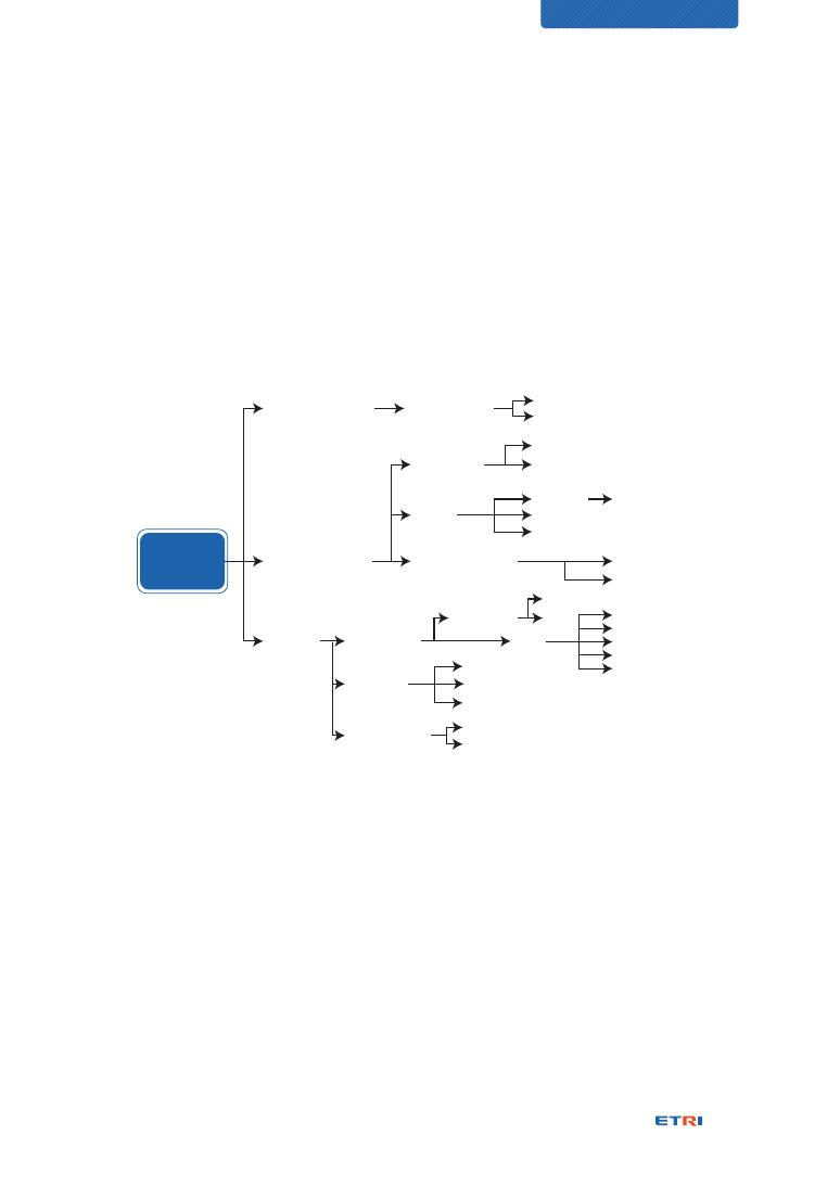
73
CHARACTERIZATION OF DIGITAL TWIN
Static models in various resolutions are mainly expressed as polygons or point clouds,
and have various properties such as color. The simulation is a collective term for the
behaviors of a static model. Various performance indicators that appear through the
animation of the static model movement and the interaction with the surrounding
environment should be visualized. Since the flight simulation, for example, composes
a physical model and a digital model, the user interface between the digital model and
the user is also an element of visualization.
Digital
Twin
Interface
(Data stream)
Physical asset
User interaction
User input
Information to user
Operational data
Analytics results
Resolution
LoD
Latency
Fidelity measure
Control from physical asset
Control from avatar
Shape
Polygon
Solid model
Surface model
Points cloud
Visual property
Shape
Texture
Color
Post-processor of CAE
Scientific visualization
User input
Information to user
Animation
Sensor data
Fidelity
Control parameters
Static model
Simulation
User interaction
Avatar
Figure 24 – Classification of terminologies of Digital Twin visualization [24]
12.2. Space fidelity measure: Resolution
The resolution of Digital Twin visualization affects how much conforming a digital replica is
to look like its physical entity closely. The higher the resolution, the more visually the digital
replica resembles the physical entity in appearance.
The Dot Per Inch (DPI) represents the resolution of a printer of raster graphics type. The
vector graphics were popular during the early years of computer graphics, but most current
graphics are based on raster graphics. The resolution of display sets the conformance level
of the digital replica to the physical entity in terms of spatial resolution. Figure 25 shows
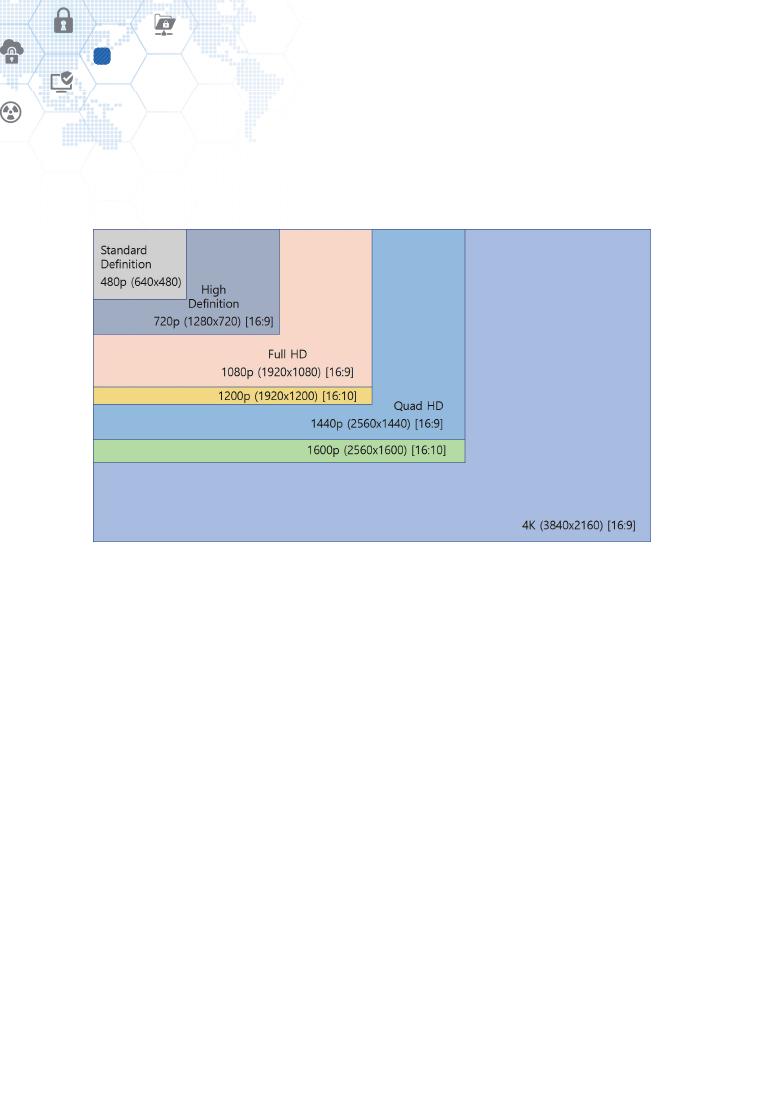
74
Digital Twin visualization fidelity
12
different display resolutions on the TV or beam projector market. The video’s resolution
refers to the size of the video and the display resolution [25].
Figure 25 – Video file resolution
Together with the mesh size of a digital model, the number of meshes matters with
the model’s visualization. Also, the density of a point cloud matters the fine detail of
representing the corresponding physical entity.
3D printing and 3D laser scanning, which have recently been under research and
development, also require a visualization model. In addition to the traditional CAD or mesh
models, point cloud models are also being introduced. Depending on the fidelity of the
Digital Twin, different levels of detail (LoD) are being used, as shown in Table 7 [26].
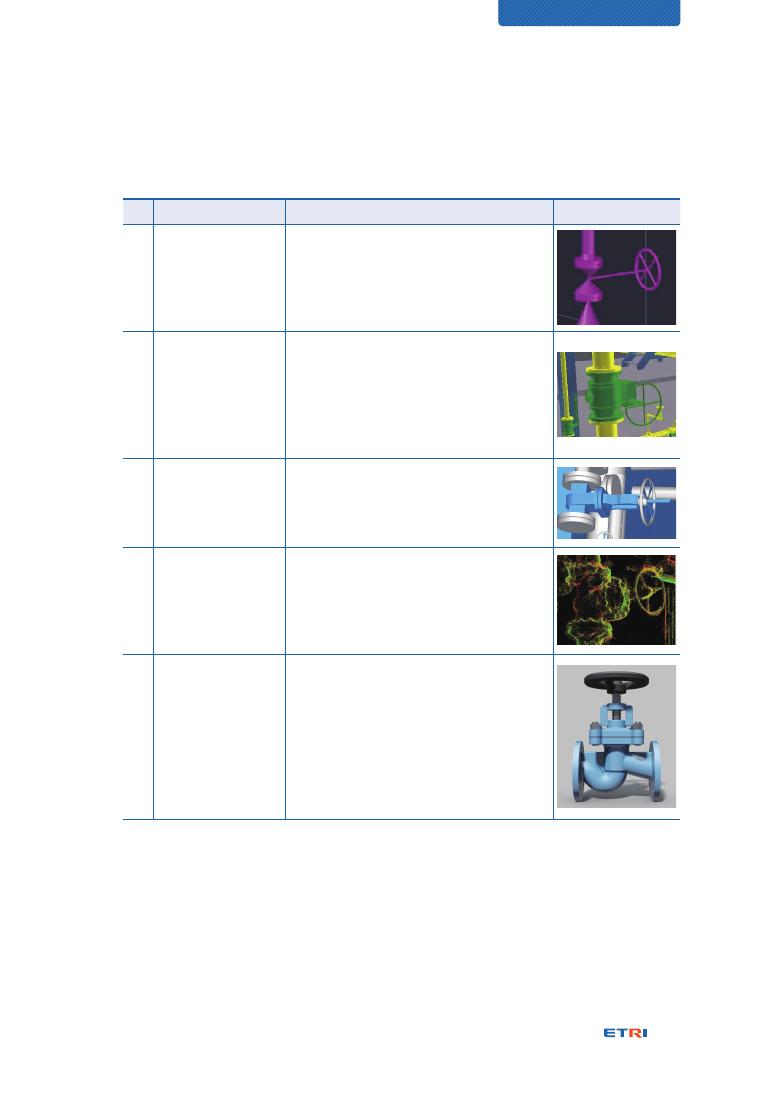
75
CHARACTERIZATION OF DIGITAL TWIN
Table 7 – Classification of plant equipment models based on the level of detail (LoD) [26]
LoD
Type
Description
Description
1
Symbol-level model
(Basic design stage,
send to equipment
manufacturer)
ㆍ Simple model
(3-dimensionalized symbol from P&ID)
ㆍ Model in default libraries (known as catalog
model) provided by a plant CAD system
2
Production model
(Production design
stage of plant)
ㆍ A model that a plant manufacturer re-
models based on vendor-package (ranges
from a collection of 2D drawings to detail
3D model) of equipment (LoD 5)
ㆍ Product model suitable for plant
construction
3
Handover model
(Reconstructed
model
from scanned data
ㆍ A model that a plant owner or operating
company requests
ㆍ Different LoD depending on the requests
4
Scanned model
(during or after
construction
of plant)
ㆍ A point cloud model from 3D scanning
during or after construction of the plant
ㆍ Additional materials shown, such as
insulation material surrounding the
equipment
5
Detailed model
from equipment
manufacturing
(Vendor)
ㆍ Detail model of the vendor for producing
the equipment
ㆍ Contains detail (geometric, non-geometric)
information about the equipment, e.g.,
internal geometry as well as detailed
surface information
ㆍ Due to security issues, only vendors have
the model.
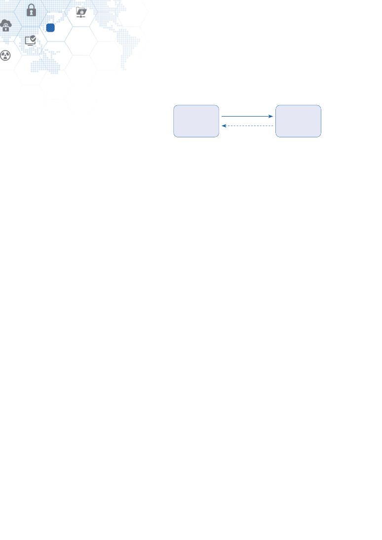
76
Digital Twin visualization fidelity
12
12.3. Time fidelity measure: Latency
The network latency refers to the time
it takes for a request to travel from
the sender to the receiver and for the
receiver to process that request. In
other words, the round-trip time from
the browser to the server [27].
The latency is not the only measure for network communication. The other ones are
bandwidth and throughput. When referring to a pipe through which water flows, it is
easier to visualize how each term works [27]:
⊙ Latency determines how fast the contents within a pipe can be transferred from the
client to the server and back.
⊙ Bandwidth determines how narrow or wide a pipe is. The narrower it is, the less data
can be pushed through it at once and vice versa.
⊙ Throughput is the amount of data that can be transferred over a given time period.
If the latency in a pipe is low and the bandwidth is also low, it means that the throughput
can be inherently low. However, if the latency is low and the bandwidth is high, that can
allow for greater throughput and a more efficient connection. Ultimately, latency creates
bottlenecks within the network, thus reducing the amount of data that can be transferred
over a period of time [27].
The network latency affects Digital Twin visualization where twinning, twinning rate,
display latency, and visualization latency are engaged.
Twinning
The twinning is “simply” the act of synchronizing the virtual and physical states, for
example, the act of measuring the state of the physical entity and realizing that state
in the virtual environment such that the virtual and physical states are “equal,” in that
all of the virtual parameters are the same value as physical parameters [10]. The time
taken for one twining is affected by the visualization latency time.
Physical Twin
Digital Twin
Latency time, 1.1s = 500ms + 600ms
Figure 26 – What is latency?
Data
500ms
Process
600ms
Information

77
CHARACTERIZATION OF DIGITAL TWIN
Twinning rate
The twinning rate is the frequency with which twinning occurs. In other research
papers, this twinning rate is only described as being in “real-time”; that is, a physical
state change can near-instantly reflect the same change in the virtual state. The value
of a near real-time state is that it enables the digital replica and physical asset to
act both simultaneously and together, and theoretically results in a near real-time
response to change [10].
Referring to NOTE 1 of Level 2 of “Details of Digital Twin maturity levels (p. 84),”
real-time depends on timeliness requirements. If human operators intervene in
twinning between a digital replica and its physical entity or interact with them through
Augmented Reality and Mixed Reality technologies, timeliness for human sense can
be critical for all interactions.
Display lag or latency
It refers to the difference between the time there is a signal input and the time it takes
the input to display on the screen. The display lag contributes to the overall latency in
the interface chain of the user’s inputs (mouse, keyboard, etc.) to the graphics card to
the monitor. Depending on the monitor, display lag times between 10~68 ms have
been measured. However, the effects of the user’s delay depend on each user’s own
sensitivity to it [28].
Visualization latency
This document defines the visualization latency as the difference between the time
an operator executes an action at a digital replica and the time the digital replica gets
feedback from its counterpart physical asset and displays it on the screen. Every
interface and processing time for display latency, user’s inputs, internal processing in
the Digital Twin system, network latency for sending and receiving, and processing
for receiving and prompt responding of the reception in the physical asset is to be
accumulated to the visualization latency time.
NOTE 1: A simple use scenario for a whole Digital Twin system of Figure 24 can justify
why visualization latency is concerned. Turning on a light in its physical asset may be
an immediate response without the physical asset’s information processing. Pressing
the light switch on the GUI screen of the digital replica system, the signal is transmitted
to the physical asset system, the light is turned on, this response is transmitted back

78
Digital Twin visualization fidelity
12
to the digital replica system, and the result is displayed on the GUI screen. The time
until the light switch is pressed at the digital replica and the result of the physical asset
is displayed is concerned with evaluating the processing responsiveness of the whole
system of digital replica, physical asset, and their interfaces.
NOTE 2: The internal processing time of the digital replica excludes any behavior
simulation but includes only the time of signaling interfaces to the peer physical asset.
NOTE 3: The processing time of the physical asset shall be limited to include only the
time of signaling interfaces for responding to the peer digital replica, i.e., the touchdown
and confirmation time at the physical asset. Additionally, other time consumption
instances take place, for example, actual execution time while performing a behavior
operation ordered, display latency on the control panels, any human intervention, and
producing time of feedback. These time consumptions shall be excluded in accounting
for the visualization latency.

79
CHARACTERIZATION OF DIGITAL TWIN
13. Digital Twin maturity model
Here the Digital Twin maturity model aims at providing an assessment tool for understanding
what levels Digital Twins are at and aspires to establish a continuous improvement plan
towards higher levels.
13.1. An existing maturity spectrum
There is an existing maturity model as follows [29]:
Table 8 – An existing Digital Twin maturity model [29]
Maturity element
(logarithmic scale)
Defining principle
Outline usage
5
Autonomous operations and
maintenance
• Complete autonomous operations &
maintenance
4
Two-way data integration and
interaction
• Remote & immersive operations
• Control the physical from the digital
3
Enrich with real-time data
(e.g., from IoT sensors)
• Operational efficiency
2
Connect model to persistent (static)
data, metadata, and BIM Stage 2
(e.g. documents, drawings, asset
management systems)
• 4D / 5D simulation
(i.e., time and cost additionally to 3D)
• Design / asset management
• BIM Stage 2
1
2D map/system or 3D model
(e.g., object-based, with no
metadata or BIM (Building
Information Modeling))
• Design/asset optimization and
coordination
0
Reality capture
(e.g., point cloud, drones,
photogrammetry)
• Brownfield (existing) as-built survey

80
Digital Twin maturity model
13
“Broadly, the spectrum of a twin can be organized into six identifiable elements. Although
each element may increase in complexity and cost, it’s neither a linear nor a sequential
process, so a twin might possess early or experimental features of higher-order elements
before possessing the lower-order, foundational ones.
The lower elements are fundamentally the creation of an accurate, as-built data model
of the asset or system. These models can be connected to static data, metadata, and
BIM, and then further enriched with real-time data. Finally, with additional sensor and
mechanical augmentation, two-way integration and interaction can begin. This allows
a digital twin to alter the state and the condition of the physical asset. Ultimately, this
system could become completely autonomous in its operations, evolving to manage the
asset through total integration between the physical and digital worlds [30].”
All the maturity models cannot provide the right answers but only guidelines for reference.
Although the maturity levels of Table 8 above are somewhat different from those of
Table 11 below, both of them can be complementary with each other and referred to for
reference. The following table is given for comparison:
Table 9 – Comparison of Digital Twin maturity models of Atkins/IET and ours
Maturity model of Table 8
Proposed maturity model of Table 11
Level 5 – Autonomous operations and maintenance
Level 5 – Autonomous Digital Twins
Level 4 – Two-way data integration and interaction
Level 2 – Static Digital Twin
Level 3 – Enrich with real-time data
Level 2 – Connect model to persistent (static) data,
metadata, and BIM Stage 2
Level 1 – Look-alike Digital Twin
Level 1 – 2D map/system or 3D model
Level 0 – Reality capture
13.2. Another maturity model by Gartner
Gartner provided a research document, “Use the IoT Platform Reference Model to Plan
Your IoT Business Solutions,” September 2016, that contains the three levels of Digital
Twin realization as follows [31]:

81
CHARACTERIZATION OF DIGITAL TWIN
Table 10 – Comparison of Digital Twin maturity models of Gartner and ours
Gartner’s maturity model
Proposed maturity model of Table 11
N/A
Level 5 – Autonomous Digital Twins
N/A
Level 4 – Interactive Digital Twins
Level 3 – Analysis, prediction, and optimization Level 3 – Dynamic Digital Twin
Level 2 – Real-time monitoring
Level 2 – Static Digital Twin
Level 1 – 3D visualization and simulation
Level 1 – Look-alike Digital Twin
The FunctionBay explained Gartner’s maturity levels as, “The difference between Level 1
and Level 2 is whether or not online methods are used to collect the data that is to be input
into the model. Using offline data to conduct simulations in advance, thereby allowing for
3D visualization, is Level 1. Level 2 involves models applying online data obtained from
sensors on actual objects through the use of IoT platforms. At this level, the object and
the model are both subject to the same experiences, so the actual object and the digital
twin can be seen as a 1:1 match. Level 3 involves the use of input data and results to
predict results in the future [32].”
The maturity model of Gartner is almost identical to part of our proposed maturity model,
Table 11. Level 1, Level 2, and Level 3 of both maturity models are the same, but Level 4
and Level 5 of Table 11 are additional.
13.3. Proposed Digital Twin maturity model
We have developed another Digital Twin maturity model from the perspective of functional
elaboration that can make a Digital Twin as close to its Physical Twin as possible as follows:

82
Digital Twin maturity model
13
Table 11 – Digital Twin maturity model from elaboration perspective
Maturity
level
Name
Functional requirements of elaboration
Examples
5
Autonomous
Digital Twins
• Autonomous operations by live synchronization and
orchestration without any human intervention
N/A
4
Interactive
Digital Twins
• Federated, synchronized, and interactive operations
among Digital Twins, but through human intervention
for action
• Synchronization through an interface bus (e.g., Digital
Thread) along Physical Twin life-cycle
N/A
3
Dynamic Digital
Twin
• Behaviors and dynamics modeled for operation and
simulation
• What-if simulation provided
• Cause analysis by reproductive simulation
• Synchronization through a data link (e.g., MTConnect,
OPC-UA, DDS) during operation time
CAE,
Digital
Factory,
Virtual
Singapore,
HILS, CPS,
etc.
2
Static Digital
Twin
• Persistent, static, and initial data connection
• No models of behaviors and dynamics but process
logics applied
• Realtime monitoring
• Partial automatic control, but mainly through human
intervention for action
SCADA,
DCS,
CAM, etc.
1
Look-alike
Digital Twin
• Physical entity modeled to have a similar visual
appearance and rendered in 2D or 3D
CAD, etc.
NOTE 1: Lower levels are inclusive in their higher levels. That is, Level 5 includes all the
lower-level functions, as depicted in Figure 8 (p. 38).
NOTE 2: Referring to “Digital Twin interface – The Third Element (p. 59),” even though
the third element of Digital Twin is the data interface as mandatory, the proposed
maturity model takes it as optional to accommodate market situations. For example,
the Virtual Singapore hasn’t built data connections between virtual Singapore objects and
corresponding physical objects, but it has lots of virtual models for simulation, and people
conceive the Virtual Singapore as a Digital Twin city. CAE (Computer-Aided Engineering)
is also the same case.

83
CHARACTERIZATION OF DIGITAL TWIN
Market situations have to be considered to model maturity levels.
No Digital Twin before at Level 1 and Level 2
The Digital Twin is not a technical term for describing and indicating a standard
specification such as Wi-Fi, ZigBee, OCF, OneM2M, and OPC, but is a conceptual
term for analysis, design, operation, and management. This is why people often
describe the Digital Twin a little differently from a technical and functional perspective.
The functions of Level 1 and Level 2 haven’t been branded as Digital Twin before it
penetrated the market and was popularized. Sometimes they were introduced as
IoT technologies and solutions, and sometimes as remote monitoring and control
solutions.
As the Digital Twin has emerged and made ample business opportunities, technology
solution providers for Level 1 and Level 2 have introduced that their product solutions
can realize Digital Twin applications. It cannot be said as wrong because there is no
standardized and allowed usage of the Digital Twin.
There is a real story. A SCADA system has been installed for a physical facility, and the
facility’s status information is displayed on a management screen so that the facility’s
operational status and control information look similar to the concept of Digital Twin.
Then, some engineering staffs of the facility asked, “why not it is a Digital Twin?”
The proposed Digital Twin maturity model has adopted these usages of Digital Twin
into Level 1 and Level 2.
The 3rd element of Digital Twin, i.e., data interface, is not mandatory but optional.
Referring to “Digital Twin interface – The Third Element (p. 59),” even though the third
element of Digital Twin is the data interface as mandatory, the proposed maturity
model takes it as optional to accommodate market situations. For example, the
Virtual Singapore hasn’t built data connections between virtual Singapore objects and
corresponding physical objects, but it has lots of virtual models for simulation, and
people conceive the Virtual Singapore as a Digital Twin city. CAE (Computer-Aided
Engineering) is also the same case.

84
Digital Twin maturity model
13
13.4. Details of Digital Twin maturity levels
Level 1: Look-alike Digital Twin
(2D or 3D models are rendered dimensionally for a physical object.)
⊙ Physical entity modeled to have a similar visual appearance and rendered in 2D or
3D: a physical object is rendered dimensionally as a 2D or 3D representation model
and can be visualized in a cyber world as in the real.
⊙ Example technology solutions: 2D/3D design tools and CAD (Computer-Aided
Design) systems are typical example solutions of Level 1.
NOTE: Level 1 doesn’t assume any data connection as required.
Level 2: Static Digital Twin
(A processing system monitors and controls a physical object through fixed
processing logics.)
⊙ Persistent, static, and initial data connection: overall operation environments of
Level 2 are static. A processing system, represented as a Digital Twin of Level 2,
is initially connected to its target physical system and its processing logics and
data connection are persistent and fixed during its life unless they are rebuilt or
recommissioned.
⊙ No models of behaviors and dynamics but process logics applied: there are no
dynamics and behavioral models of a physical object, but step-by-step processing
logics, comprised of real-time monitoring and reactive control, to the physical
object are developed and work during operation time.
⊙ Real-time monitoring: status data from the operation of physical objects are
delivered to processing logics for monitoring, and reactive controls can be made.
NOTE 1: Here, the real-time needs to be clarified because it may be interpreted
differently by application requirements. For example, a remote metering application
required 15 minutes for real-time responses. The timeliness of real-time depends
on applications.
NOTE 2: A real-time operation may consist of real-time monitoring and reactive
control. The reactive control may be performed automatically by management
logics, or manually by human intervention. Automatically-reactive control can

85
CHARACTERIZATION OF DIGITAL TWIN
enable real-time operation. But the manually-reactive control cannot, due to
human engagement taking more time.
NOTE 3: Real-time monitoring requires data interface technologies. There are lots
of different interface solutions such as MTConnect, OPC-UA, PROFIBUS, Modbus,
and RAPIEnet, where the timeliness of real-time may vary according to application
requirements.
⊙ Partial automatic control but mainly through human intervention for action: in case
that the operation and control of a physical system are very stable and reliable, and
any problem that may occur even if operated automatically is not serious, reactive
controls against real-time monitoring can be performed automatically. A part of
the system can take advantage of automatic control. But the operation and control
of the whole system haven’t been matured to fully automatic control so that it is
performed primarily by human intervention.
NOTE 1: The human-intervened operation is a type of Human-in-the-Loop in
which a human operator should engage the loop operation process between a
physical object and its Digital Twin.
NOTE 2: Status information by monitoring, control actions, and reactive responses
are visualized on display.
⊙ Example technology solutions: SCADA (Supervisory Control And Data Acquisition),
DCS (Distributed Control System), CAM (Computer-Aided Manufacturing) are
typical example solutions of Level 2. They have been used and proved reliably for
a long time in various industries through a twin-like HMI (Human-Man Interface).
Level 2 adopted this market situation.
NOTE: The Digital Twin maturity model doesn’t require data interface as mandatory,
as stated above. But every Level 2 use case for those required functions is based on
a data interface, and Level 2 can specify the data interface as mandatory.
Level 3: Dynamic Digital Twin
(A represented virtual model can simulate its corresponding operation to its physical
object.)
⊙ Behaviors and dynamics modeled for operation and simulation: in addition to
dimensional representation models for physical objects, their behaviors and

86
Digital Twin maturity model
13
dynamics for operation are characterized and represented as virtual models at
Level 3. The fidelity in terms of resolution of characterization of the physical objects
depends on modeling purposes.
⊙ What-if simulation provided: virtual models comprising a Digital Twin can simulate
certain situations by arbitrary input parameters for its physical object. Simulation
results as output can help understand how the physical object behaves for its
future situation.
⊙ Cause analysis by reproductive simulation: virtual models of a Digital Twin can
simulate reproductively what happened to its physical object. Reproductive
simulation results can help analyze why it happened.
⊙ Synchronization through a data link (e.g., MTConnect) during operation time: virtual
models of a Digital Twin are synchronized with its physical object, but interactions
for action between them aren’t made all the time concurrently. People intervene for
sure to execute an action to the physical object because autonomous action by a
Digital Twin system may cause significant problems in the real world.
NOTE 1: The synchronization refers to the act of synchronizing the virtual and
physical states, for example, the act of measuring the state of the physical object
and realizing that state in its Digital Twin such that the virtual and physical states
are ‘equal,’ in that all of the virtual parameters are the same value as physical
parameters [10].
NOTE 2: There are lots of data link technologies which can support synchronization
between Digital Twin and Physical Twin, i.e., physical object. Their examples are
MTConnect, PROFIBUS, Modbus, RAPIEnet, CC-Link, EtherCAT, and so on.
⊙ Example technology solutions: CAE (Computer-Aided Engineering), Virtual
Singapore, Digital Factory, HILS, and CPS are typical example solutions of Level
3. CAE and Virtual Singapore have various behavioral and dynamics models for
operation and can support simulation of particular situations with different input
parameters where no data connection is engaged. Digital Factory, HILS (Hardware-
in-the-Loop Simulation), and CPS (Cyber-Physical System) also have various
behavioral and dynamics models for operation and can support relevant simulation
cases, but data connections are engaged.
NOTE: The Digital Twin maturity model doesn’t require data interface as mandatory

87
CHARACTERIZATION OF DIGITAL TWIN
but optional, as stated above. Thus, the synchronization doesn’t happen all the time.
Level 4: Interactive Digital Twins
(Multiple Digital Twins are federated each other and perform mutual interactions for
their cross-dependent operations.)
⊙ Federated, synchronized, and interactive operations among Digital Twins, but
through human intervention for action: while the usage of Digital Twin of Level 1,
Level 2, and Level 3 has been presented as singular, the usage of Digital Twin of
Level 4 is presented as plural, i.e., “Digital Twins,” and Level 4 deals with the cases
that a Digital Twin affects other Digital Twins and multiple Digital Twins interact
with each other.
NOTE: It may be said that the federation of multiple Digital Twins is considered
simply as additional output and input from a Digital Twin to other Digital Twins,
i.e., additional interaction relationships among them. However, this is not a simple
connectivity issue but an integration and convergence issue among different
domains, which means different worlds are coupled closely and interact with each
other. It is a big step and can cause a big challenge to orchestrate their mutual
interactions among them.
⊙ Synchronization through an interface bus (e.g., Digital Thread) along Physical Twin
life-cycle: as described in Level 3, people should intervene for sure to execute an
action to other Digital Twins and associated physical objects. The synchronization
of Level 3 is performed, but additional synchronization is performed among all
engaged Digital Twins along a physical object’s life-cycle.
NOTE: The interface bus refers to a data exchange channel over all engaged
domains threaded for communication. The Digital Thread is a typical example of
the interface bus. It is expected that OPC-UA or DDS (Data Distribution Service)
can be extended to realize the interface bus.
Level 5: Autonomous Digital Twins
(Physical objects and their Digital Twins are synchronized in real-time and interact
with each other through autonomous orchestration without manual interventions.)
⊙ Autonomous operations by live synchronization and orchestration without any
human intervention: Level 5 assumes that the mutual relationship between
structure and behavior models of a physical object and the corresponding virtual

88
Digital Twin maturity model
13
models of the Digital Twin is stable, reliable, and dependable for action to the real
world. In the case, physical objects and their Digital Twin models are synchronized
in real-time and interact with each other through autonomous and live orchestration
without manual interventions. The time constraints of real-time depend on
application requirements, as described in NOTE 1 of Level 2. For example, for
visual synchronization with people, real-time needs to be up to 10 msec. The live
orchestration refers to timely synthetic alignments between the physical objects
and their participating Digital Twins. The autonomous operation means no manual
interventions are required for execution to the physical objects.
13.5. Digital Twin evolution with the maturity model
Dr. Sanjay Ravi has introduced the evolution of the Digital Twin according to its time phases
[33], as captured in Table 12 below. Following the figured time phases, Level 1 and Level
2 functions belong to the “Information Mirroring Model” phase, and Level 3 functions are
associated with the “Digital Simulations, 3D Printing” phase but also with the phases of
the “Intelligent and Connected IoT Services” and the “Mixed Reality, Cognitive and AI” as
well. Because the technical features of the last two phases are somewhat sophisticated
technologies that can support a higher quality of processing and operation, Level 3 may
take advantage of them for better performance and higher quality. The required functions
of Level 4 and Level 5 haven’t been presented yet in the market. The next stages of the
Digital Twin evolution may encompass them.
It should be noted that the lower maturity levels don’t mean old and obsolete technology
features but different levels of functional requirements. For example, as a technology
solution of Level 2, RS-485 is still well working for monitoring and control in various
industries and may be part of a large-scale Digital Twin system of Level 5.

89
CHARACTERIZATION OF DIGITAL TWIN
Table 12 – Time phases and maturity levels of Digital Twin [33]
Information Mirroring
Model (1985-2002)
Digital Simulations, 3D
printing
(2003-2014)
Intelligent and
Connected IoT services
(2014-2016)
Mixed Reality,
Cognitive and AI
(2017~)
- Digital Twin as
concept
- R&D and
engineering focused
- Dedicated
workstations and
servers
- Collaboration,
simulation, and
workflow across
global enterprise
- Browser and web
access
- Connected devices
– Data unification
between physical
and virtual worlds
- IoT, big data
analytics, cloud
- Holographics and
AR/VR
- Cognitive services
- Artificial intelligence
- Powerful 3D
modeling and
analysis
- Remote
programming CNCs,
robots, …
- Digital design,
virtual assembly,
and simulation
before physical
commitment
- 3D printing goes
mainstream
- Rapid feedback
across design,
manufacturing,
operation
- Products augmented
with digital services
- Guided interactions
- Blended human-
machine
collaboration
- Autonomous and
self- healing
Level 1 and Level 2
Level 3

90
Digital Twin and other relevant technologies
14
14. Digital Twin and other relevant technologies
Referring to the clause, “Digital Twin interface – The Third Element (p. 59),” this clause
has summarized similar and different points concerning other similar technologies such
as CPS, VR, AR, MR, and flight simulation.
14.1. Cyber-Physical System
We would like to provide three existing definitions of CPS. Wikipedia provides:
⊙ “a computer system in which a mechanism is controlled or monitored by computer-
based algorithms. In cyber-physical systems, physical and software components
are deeply intertwined, able to operate on different spatial and temporal scales,
exhibit multiple and distinct behavioral modalities, and interact with each other in
ways that change with context [35].”
The framework for Cyber-Physical Systems of the NIST defines it as:
⊙ “smart systems that include engineered interacting networks of physical and
computational components [36].”
The NSF defines it as:
⊙ “referring to the tight conjoining of and coordination between computational and
physical resources [37]”;
⊙ “engineered systems that are built from and depend upon the synergy of
computational and physical components [38]”; and
⊙ “engineered systems that are built from, and depend upon, the seamless integration
of computational algorithms and physical components [39]”;
The word CPS appeared with a logically similar concept to the Digital Twin in embedded
systems around 2006. CPS has been used in many areas where embedded systems
have been deployed since the President’s Council of Advisors on Science and Technology
(PCAST) declared CPS as a national priority in 2007. In the vision of the 4th Industrial
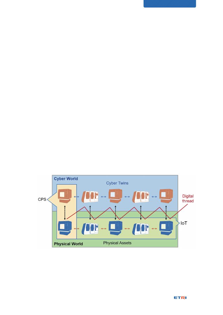
91
CHARACTERIZATION OF DIGITAL TWIN
Revolution, which originated in Germany to promote manufacturing innovation, CPS has
been listed as one of the core technologies.
Our analysis has produced the following study results from three perspectives: engineering
view, market acceptance view, and intuition view.
Analysis by engineering view
Figure 27 depicts a typical CPS configuration that consists of cyber and physical worlds
and digital thread for their integration interface. The IoT supports inter-connections of
physical assets, i.e., physical entities. The construction of CPS is very similar to that
of the Digital Twin. Although current speculations say that the Digital Twin is a part of
CPS or an implementation case of CPS, or vice versa, this Technical Report finds out
that they are similar conceptually but have “the coverage difference.”
NOTE: It has been said occasionally that Digital Twin is an implementation instance
of CPS; CPS is one of enabling technologies for Digital Twin; Digital Twin is the core
technology of CPS [41]; or, even both are the same. The reason is that there are no
standard specifications for CPS and Digital Twin, and people may interpret them in
their expertise.
Figure 27 – Use case of CPS and digital thread in manufacturing [40]
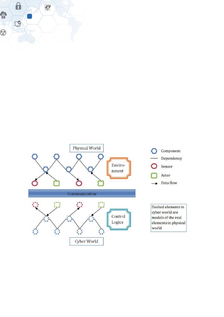
92
Digital Twin and other relevant technologies
14
Figure 27 illustrates how the digital thread works and where it is located within the physical
and cyber worlds. CPS has a digital thread that connects the worlds physical and cyber.
Figure 27 shows multiple cyber twins, physical assets, and the IoT that integrates physical
assets. The digital thread, however, is not an exclusive technology term only for CPS. It
has been said that the digital thread is one of the key enabling technologies for the Digital
Twin as well.
Figure 27 describes that:
⊙ two peer entities are coupled between the cyber and physical worlds via CPS;
⊙ a set of CPS systems for multiple devices can be possible within a manufacturing
domain; and
⊙ CPS systems are inter-related through the digital thread.
Figure 28 – A typical CPS [42]

93
CHARACTERIZATION OF DIGITAL TWIN
The configuration of Figure 27 looks very similar to typical configurations of the Digital
Twin. But the Digital Twin covers the whole life-cycle phases with integrating many
other Digital Twin systems along the entire life-cycle. Here “the coverage difference”
has been identified between them. It hasn’t been observed that CPS aims at covering
the whole life-cycle stages for products.
However, the coverage difference viewpoint cannot be reliable because technology
experts explain CPS in their own expertise and a little different illustration image.
Figure 28 shows another illustration view of CPS. The integration boundary may be
expanded outside to other domains, which means the CPS federation boundary may
be approaching to that of the Digital Twin. That is, it can be said that they have the
same coverage view.
Analysis by market acceptance
Even though the initial understandings of CPS and Digital Twin looked very similar
or identical by their business stakeholders, the characteristics and technical features
of the Digital Twin have been more evolved so far and dealing with more elaborated
features than those of the CPS. The more stakeholders and people are coming up
the market, the more additional and new ideas apply to the Digital Twin and the more
opportunities the Digital Twin will take.
The diversity also is inducing evolutions.
NOTE: The number of Google search results for CPS is 54,600,000; 149,000,000 for
Cyber-Physical System; and 494,000,000 for Digital Twin as of August 17, 2020.
Analysis by intuition view
The fast market penetration and current popularity of Digital Twin can be said to be
thanks to an intuitive name that anyone can quickly understand. For an unfamiliar
concept to survive and spread in the business ecosystem, a virtuous cycle of
acceptance and investment induces shall be created. The Digital Twin can be easily
understood by anyone, including investors from even humanities background, and
mirror-image twins inspire people to trigger more diverse use cases. On the other
hand, the Cyber-Physical System has a barrier to its name so that capital investors,
purchasing decision-makers, and others need a considerable amount of time to
understand it, compared to those with an engineering background.
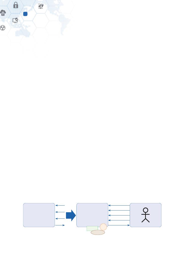
94
Digital Twin and other relevant technologies
14
Short conclusion
Consequently, it can be said that the Cyber-Physical System and Digital Twin are identical
to each other while realizing their applications by sharing the same enabling technologies.
They can accommodate new features and technologies because they are not standard
technologies with technical specifications and cannot be defined with exclusive meaning,
finally resulting in having the same identity.
Then, we prospect the Digital Twin would be more popularized in the future with more
opportunities for additional and advanced features and business aspects in many industry
domains.
14.2. Virtual Reality
The Virtual Reality can share the vital technical elements used to realize the Digital Twin
and may look similar in part, but it should not be classified as a kind of Digital Twin.
Wikipedia reads, “Virtual reality (VR) is a simulated experience that can be similar to or
completely different from the real world [43].” The “similar” refers to reflecting a physical
object’s structure and resembling what the physical object does and possibly through any
deviation, tweaking, and imagination.
The Digital Twin shall be based on the real world and limited to the physical objects in
reality. Referring to the FBS framework, the Digital Twin in Figure 20 is a digital replica
from the Physical Twin, of which structure and behaviors are virtualized and represented
as the Digital Twin via a set of modeling processes by intended purposes. The Digital Twin
can be mathematically formulated as “X1 = f(a, b, c)” for easier understanding while the
whole structure, behaviors, and personality of the Physical Twin can be formulated as “X
= f(a, b, c, d, e).”
Physical Twin
{X = f(a, b, c, d, e)}
Virtual Reality
{X1 = f(a, b+, c-, g)}
a
a
b+
c-
g
x1
b
c
x1
Emulated according to
Function (purpose)
c-
b+
g
Figure 29 – Conceptual interface model for Virtual Reality
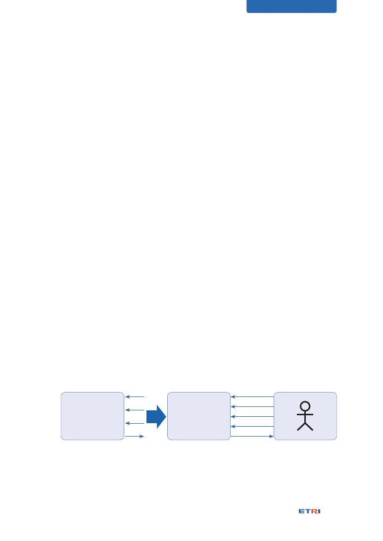
95
CHARACTERIZATION OF DIGITAL TWIN
Compared to Figure 20, the interface model for Virtual Reality is provided in Figure 29. The
structure and behaviors of the Physical Twin may be partly or wholly emulated into the
Virtual Reality by intended purposes. Also, imaginary additions or subtractions are possible
while being emulated because structural and behavioral conformance to the Physical Twin
doesn’t matter. Such Virtual Reality model can be mathematically formulated as “X1 = f(a,
b+, c-, g)” as shown in Figure 29 where “b+” and “c-” means their functional behavior
models are tweaked in any way, and “g” means an imaginary addition is made.
NOTE: The left side Physical Twin of Figure 29 has already been described above in
Figure 20. But directions of the interface flows are opposite. The output “X1” of Figure 29
represents a part of the whole function “X” and is produced by input “a,” “b,” and “c” while
the function “X” is performed by input “a,” “b,” “c,” “d,” and “e.”
The key difference between Figure 20 and Figure 29 is the interaction counterparts of the
Digital Twin and the Virtual Reality. While the Digital Twin interacts with its corresponding
Physical Twin, the Virtual Reality interacts with a human user. The Physical Twin of Figure 29
doesn’t interact with its emulated, tweaked, or imaginary Virtual Reality model.
Conclusively, the Virtual Reality is likely not that complementary to the Digital Twin.
14.3. Flight simulation
While the Virtual Reality emulates a physical object and contains imaginary working
scenarios and functions by purposes or executes a wholly imaginary model, the flight
simulator is strictly and precisely based on the structure and behaviors of a physical
object, i.e., flight. This is the same thing between Digital Twin and flight simulator from
the modeling perspective between real and virtual.
Physical Twin
{X = f(a, b, c, d, e)}
Flight simulator
{X1 = f(a, b, c)}
a
a
b
c
c
x1
b
c
x1
Replicated according to
Function (purpose)
Figure 30 – Conceptual interface model for the flight simulator

96
Digital Twin and other relevant technologies
14
Compared to Figure 20, the interface model for a flight simulator is provided in Figure 30.
The structure and behaviors of the Physical Twin, i.e., flight, is partly or wholly replicated
by intended purposes into the flight simulator, here mathematically formulated as “X1 =
f(a, b, c)” for a part of the whole flight functions. That is, the model for output “X1” of the
flight simulator shall be the same with “X1” of the Physical Twin.
The key difference between Figure 20 and Figure 30 is the interaction counterparts of the
Digital Twin and the flight simulator. While the Digital Twin interacts with its corresponding
Physical Twin, the flight simulator interacts with a human user. The Physical Twin of Figure
30 doesn’t interact with the flight simulator model. The flight simulator and Virtual Reality
are the same from the interaction perspective.
For a comparison between Figure 29 and Figure 30, the flight simulator’s structure and
behavior models should always be identical between its peer models, while those of
Virtual Reality may be mostly different.
14.4. Augmented Reality
Interactions between Physical Twin and Digital Twin take place actually, as shown in Figure
31, which can help clarify the concepts of Augmented Reality and Digital Twin.
Level 5 of the Digital Twin maturity model doesn’t allow human engagements for the twin
to get synchronized in real-time and adapted mutually and autonomously. But this would
be an ideal case that may come true when everything in the loop is stable, reliable, and
dependable. Figure 31 depicts an actual case for operators to intervene between both
systems to make sure to apply to the Physical Twin. When we talk about the Digital Twin
concept, we focus on the logical relationship without assuming human interventions.
Physical Twin
{X = f(a, b, c, d, e)}
Digital Twin
{X1 = f(a, b, c)}
a
b
c
x1
x1
Human intervention made,
resulting in Human-in-the-Loop
Figure 31 – Human-in-the-Loop between Physical Twin and Digital Twin
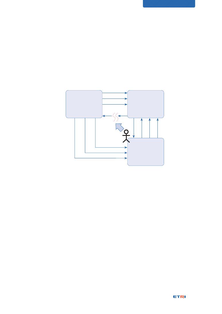
97
CHARACTERIZATION OF DIGITAL TWIN
However, the Augmented Reality shall be engaged with people, and they are part of the
whole system of Digital Twin and Augmented Reality, as shown in Figure 32.
Michael Grieves pointed out that working with Digital Twins is evolving into a mixed-mode
of working with advancements in the Augmented Reality technology, and it can enable
overlaying physical space with virtual space to work in both spaces simultaneously [6].
Physical Twin
{X = f(a, b, c, d, e)}
Digital Twin
{X1 = f(a, b, c)}
Augmented Reality
{Y = f(i, j, k)}
a
b
c
i
j
k
c'
b'
a'
x1
x1
Human-in-the-Loop
Figure 32 – Conceptual interface model for Digital Twin with Augmented Reality
The input “i,” “j,” and “k” from the Physical Twin represent visual objects in the physical
space that do not affect the behaviors of the Physical Twin. The functional model, “Y”
of the Augmented Reality system, can support visual manipulation of the functional
components constituting the Physical Twin, and the operator performs a simulation by
providing the changed values, a’, b’ and c’ to the Digital Twin system. The operator can
obtain the simulated output, X’ as a result; check that the input parameters for the Physical
Twin are not causing problems; and, trigger the Physical Twin to perform the execution,
“X1” if no problem is confirmed.
Figure 33 is an excerpt from the working draft ISO/IEC WD 3721. In a game called
Pokemon, through a transparent display such as Google Glass, it shows the relationship
between actors in the context of playing the game across the real world and the virtual
world. Figure 33 depicts the real world, the virtual world, and the link between the two
[44].
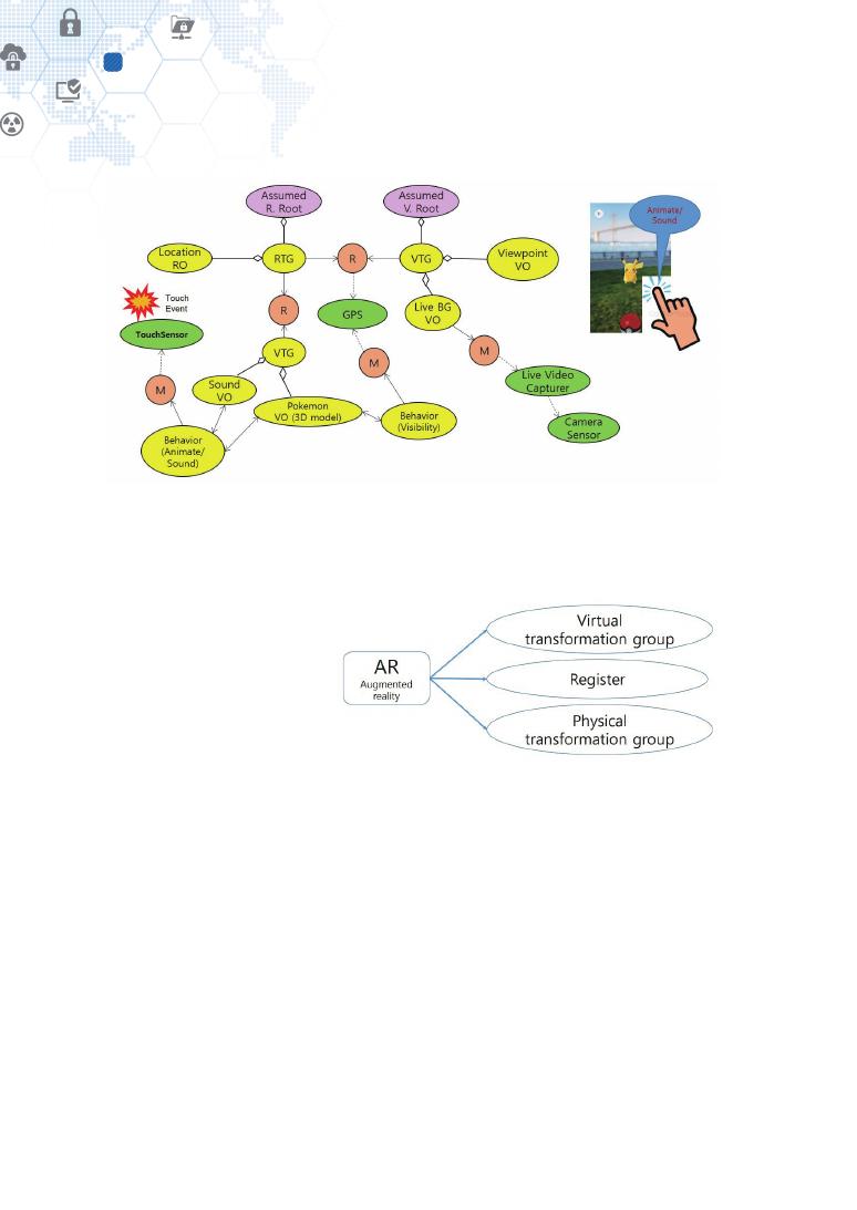
98
Digital Twin and other relevant technologies
14
Figure 33 – A content representation scenario of marker-based 3D object augmentation
for video see-through display [44]
Figure 34 shows the three-part model that composes the Augmented Reality and illustrates
a part of Figure 33. The “Register” is the act of matching the physical and virtual worlds in a
moving game. It is necessary to
match the corner of the physical
building with the corresponding
corner of the virtual building.
Similarly, it is the act of matching
the car navigation screen with
the road and surroundings of
the site. The task of “Register”
of AR is significantly useful and
essential to get coupled tightly between Physical Twin and Digital Twin with engaging human
operators within the whole collaborative system.
Michael Grieves provided two use cases for the Digital Twin with the Augmented Reality
as described in NOTE 1 and NOTE 2 below.
NOTE 1 – Cobotics [6]
Cobotics is a recent neologism that combines “robotics” with “cooperation.” This concept
describes how robots will work in cooperation with humans to perform tasks. There are
two models of this cooperation: working alongside a human and augmenting a human.
Figure 34 – Three-part model of Augmented Reality [44]

99
CHARACTERIZATION OF DIGITAL TWIN
In working alongside a human, safety is critical. If robots are to come out of fenced-in
areas and work alongside humans, then they will need to sense human presence and
avoid jeopardizing human safety.
The other role is to augment a human. This would entail a human using augmented/
virtual reality glasses to see through the robot’s eyes. The robot would mimic the human
gestures. This would allow humans to augment their natural constraints at both ends of
the spectrum. At the macro end, they could lift and position large items. At the micro end,
they could do very fine detail work.
NOTE 2 – Augmented reality [6]
The Digital Twin model has had the implication that we worked with the Digital Twin or the
Physical Twin at any point in time. Augmented Reality (AR) changes that by allowing work
to be done with both, simultaneously. In AR, the usage would be in a dynamic fashion. The
idea behind this is that a human who is working with a physical system could use information
that was being captured from the physical system and transmitted to the Digital Twin which
would then process the data, massage it, and feed it back to that human.
An example of this might be a mechanic who is looking at an airplane engine. That
mechanic might be very interested in the temperatures, airflow, and fuel flow that
occurred within that engine. The Physical Twin version of this product would be that
sensors located throughout the engine would be measuring such things as temperature,
airflow, and fuel flow and transmitting that data to its Digital Twin. The Digital Twin would
then be aggregating that information, processing, and correlating that information, such
that it would provide meaningful information to the mechanic.
The mechanic would be equipped with glasses or contact lenses so that when he or she
looked at a particular part of the engine, the Digital Twin would feed the mechanic information
about what he or she was looking at. If the mechanic was looking at the air intake area, the
Digital Twin would display on the mechanic’s glasses, the airflow at the exact point in time
that the mechanic was looking at it. The Digital Twin, when requested, could display a graph
of airflow over the period of time that the mechanic was interested in.
As the mechanic glanced at various parts of the engine, the sensors that were reading
temperatures would be displayed so that the mechanic could see the various temperature
readings. The Digital Twin might also process and display the data such that the engine
components appeared color-coded depending on the temperature gradients that were
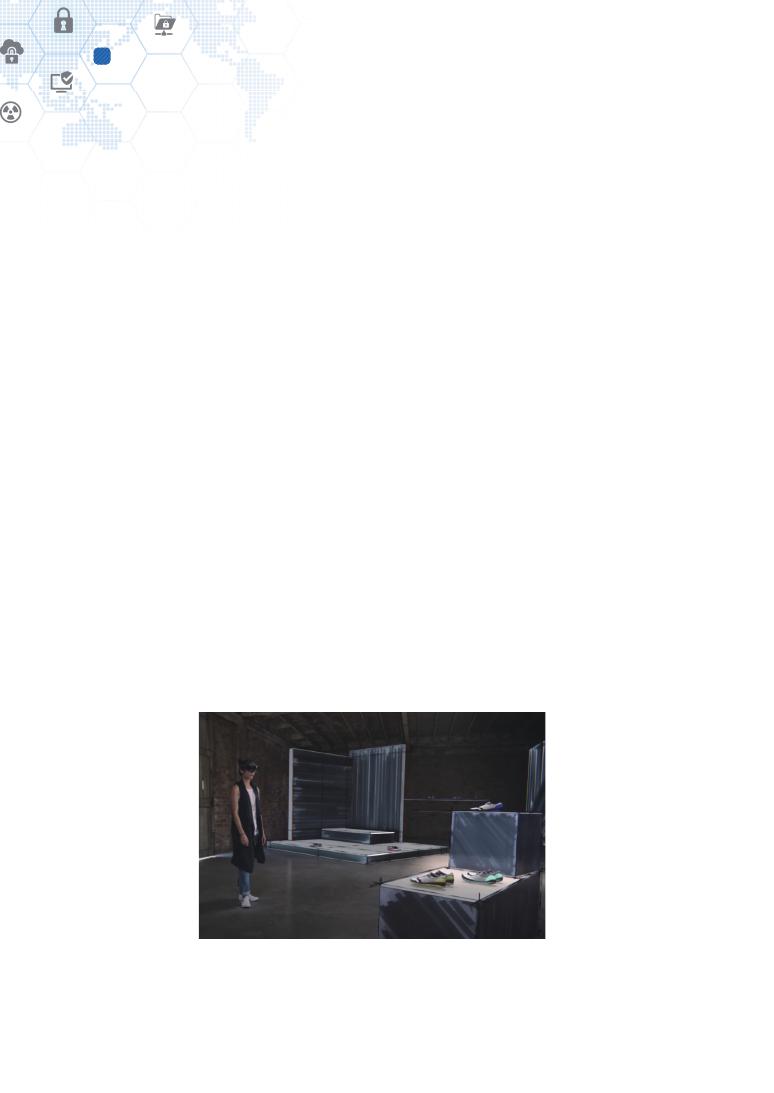
100
Digital Twin and other relevant technologies
14
occurring in the engine. So the mechanic, when looking at the engine, would see
red, yellow, or orange colors to indicate relative temperatures compared to the design
temperatures that had been predicted from that engine component.
This capture of information transferred to the Digital Twin from the Physical Twin sensors,
the Digital Twin manipulating that data, and then feeding it back as various kinds of visual
information, would be an extremely useful use case of the Digital Twin with its Physical
Twin. Augmented Reality evolves the Digital Twin model from a sequential single mode
model into an integrated multi-mode model.
14.5. Mixed Reality
Wikipedia reads, “Mixed reality (MR) is the merging of real and virtual worlds to produce
new environments and visualizations, where physical and digital objects co-exist and
interact in real-time. Mixed reality does not exclusively take place in either the physical or
virtual world, but is a hybrid of reality and virtual reality, encompassing both augmented
reality and augmented virtuality via immersive technology [45][46].”
Despite Wikipedia’s explanation of Mixed Reality, it should be noted that the concept
of Mixed Reality hasn’t been technically established, that the relationship of functional
components is not clearly understood, but that it is still being addressed from a marketing
and sales perspective. Because various use cases of Mixed Reality are not clearly
distinguished from those of Augmented Reality. The same AR application happened even
to be explained as an MR application.
Figure 35 – A use case view of Mixed Reality envisioned by Microsoft [47]
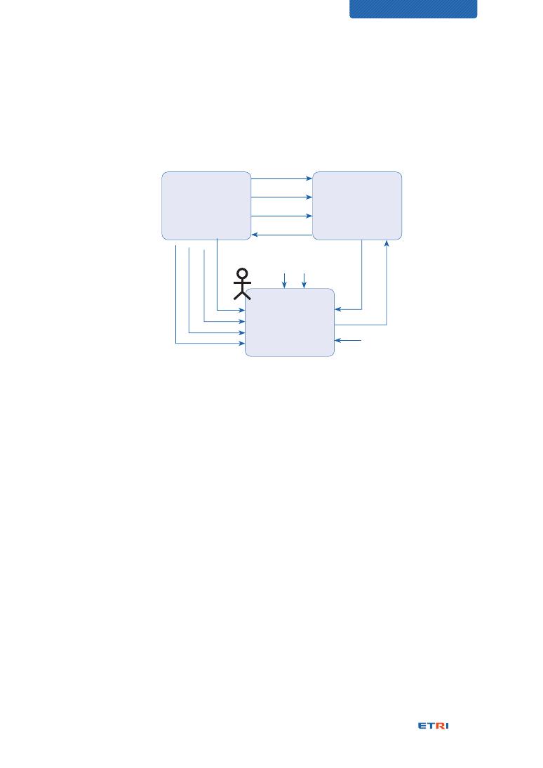
101
CHARACTERIZATION OF DIGITAL TWIN
Referring to Figure 35, the following scenarios are presented to get an MR situation and
required interfaces. The interface model for them is shown in Figure 36.
Physical Twin
{X = f(a, b, c, Y2,
X1)}
Digital Twin
{X1 = f(a, b, c, Y1)}
Mixed Reality
{Y1 = f(a, i, j, X1)}
{Y2 = f(b, i, k, X)}
a
b
c
X1
k
i
j
Y2
Y1
a
X
b
x1
Figure 36 – Conceptual interface model for Digital Twin with Mixed Reality
⊙ We would like to install new furniture and appliance in the living room space on the
second floor.
⊙ The size and color of the furniture and appliance should match the living room structure
and fit well with the furniture already installed.
⊙ We select the Digital Twin models of the furniture and appliance we want to purchase
and virtually installs them in the living room shown through AR to make sure they fit
well.
⊙ When they don’t fit well, we move the existing furniture to find a better location mix and
see the changed living room environment through AR immediately.
⊙ We check again that the furniture and appliance fit well in the changed living room.
⊙ A guest comes to the front door on the first floor and asks to open the door.
⊙ We select the Digital Twin model of the front door, check the visitor through the screen,
and opens the door by pressing the door-opening button displayed on the Digital Twin
model.

102
Digital Twin and other relevant technologies
14
⊙ The front door opens, and the guest comes in and up to the second floor to meet up.
The Mixed Reality system is believed as a circular and mixed system of Physical Twin,
Digital Twin, and people through Mixed Reality technologies, as shown in Figure 36.
While the Augmented Reality provides augmenting the visual presentation of the Physical
Twin to the Digital Twin for engaging both of them visually coupled, the Mixed Reality
provides engaging all participating entities within the overlay world of physical and virtual
worlds and enabling cross-interactions among them, resulting in a circular system of
theirs. Figure 36 illustrates a conceptual reference interface model for the circular
interaction system realized by the Mixed Reality.
14.6. Short conclusion
VR, AR, MR, and flight simulation technologies may be developed somewhat in different
ways even though they adopt part of standard technologies. It should be noted that their
reference interface models depicted at the above sub-clauses were provided for an easier
understanding of clarifying associations of related technologies. They were not precisely
but conceptually drawn, and even different configurations are possible because there are
no standardized interface specifications.
Conclusively the Virtual Reality, Augmented Reality, and Mixed Reality technologies can
be complementary to enhance the more visual, immersive, and interactive realization of
the Digital Twin with being engaged with people.

103
CHARACTERIZATION OF DIGITAL TWIN
CHARACTERIZATION OF
DIGITAL TWIN
Conclusions
Bibliography
Authors
Acknowledgments
104
105
110
112

104
Conclusions
As time goes, we expect more and more stakeholders and people are coming up to the
market, and the Digital Twin will take more opportunities. The fast penetration and current
popularity of Digital Twin are thanks to such an intuitive name that anyone can quickly
understand. The mirror-image twin of Digital Twin can inspire people to draw innovative
ideas against conventional things and trigger more diverse use cases. Then, a virtuous
cycle of acceptance and investment can be established.
Characterizing the Digital Twin federation, we have elaborated on the integration scope
of Digital Twins for being expanded from business associations to heterogeneous
associations having different problem domains with the same concerns across them.
The concept of the Multi-persona Twin was suggested together to accommodate mobile
physical entities and playing different roles at different places.
We clarified two fidelity aspects of behavioral characterization and structural characterization
called visualization. Both structure and behaviors shall be modeled appropriately according
to intended purposes. The characterizations can be performed through analysis viewpoints,
and we provided four Digital Twin modeling dimensions for them. Related measures also
were considered.
Noting that the data interface between Digital Twin and its physical entity was indicated as
the third significant element to establish Digital Twin systems, we clarified complementary
interaction between Digital Twin and other similar technologies such as CPS, VR, AR, MR,
and flight simulation according to their data interface models.
Finally, the Digital Twin maturity model was suggested to assess where a Digital Twin is
and where it should go and what it should achieve. It consists of the five levels from Look-
alike Digital Twin to Autonomous Digital Twin through Static Digital Twin, Dynamic Digital
Twin, and Interactive Digital Twin, respectively.

105
CHARACTERIZATION OF DIGITAL TWIN
Bibliography
[1]
Wikipedia, “Symmetry”, August 2020, https://en.wikipedia.org/wiki/Symmetry
[2]
Wikipedia, “Digital twin”, August 2020, https://en.wikipedia.org/wiki/Digital_twin
[3]
ISO/DIS 23247-1, “Automation systems and integration — Digital Twin
framework for manufacturing — Part 1: Overview and general principles”, ISO/
TC 184/SC 4/WG 15 (Digital manufacturing), To be published in 2021,
[4]
Michael W. Grieves, “Origins of the Digital Twin Concept,” ResearchGate, August
2016, https://www.researchgate.net/publication/307509727
[5]
Michael W. Grieves and John Vickers, “Digital Twin: Mitigating Unpredictable,
Undesirable Emergent Behavior in Complex Systems,” Transdisciplinary
Perspectives on Complex Systems (pp.85-113), August 2017, https://www.
researchgate.net/publication/306223791
[6]
Michael W. Grieves, “Virtually Intelligent Product Systems: Digital and Physical
Twins,” Complex Systems Engineering: Theory and Practice, Publisher: American
Institute of Aeronautics and Astronautics (pp.175-200), July 2019, https://www.
researchgate.net/publication/334599683
[7]
C. Kleijn, “Introduction to Hardware-in-the-Loop Simulation,” Controllab
Products B.V., https://www.hil-simulation.com/images/stories/Documents/
Introduction%20to%20Hardware-in-the-Loop%20Simulation.pdf
[8]
MindFull, “The Transformation of Things: Identity and the Clinging Mind,” Written in
Philosophy of Medium, April 2020, https://medium.com/@thatnewcarsmell101/
the-transformation-of-things-identity-and-the-clinging-mind-554e956d28b2
[9]
Ike no Taiga, “Zhuangzi dreaming of a butterfly (or a butterfly dreaming of
Zhuangzi),” WIKIART, May 2013, https://www.wikiart.org/en/ike-no-taiga/
zhuangzi-dreaming-of-a-butterfly-or-a-butterfly-dreaming-of-zhuangzi
[10]
David Jones, Chris Snider, Aydin Nassehi, Jason Yon, Ben Hicks, “Characterising

106
the Digital Twin: A systematic literature review,” CIRP Journal of Manufacturing
Science and Technology, March 2020, https://www.sciencedirect.com/science/
article/pii/S1755581720300110
[11]
Avatar wiki, “Avatar (species),” August 2020, https://james-camerons-avatar.
fandom.com/wiki/Avatar_(species)
[12]
Avatar wiki, “Hometree,” August 2020, https://james-camerons-avatar.fandom.
com/wiki/Hometree
[13]
Avatar wiki, “Eywa,” August 2020, https://james-camerons-avatar.fandom.
com/wiki/Eywa
[14]
Avatar wiki, “Pandora Neural Network,” August 2020, https://james-camerons-
avatar.fandom.com/wiki/Pandoran_Neural_Network
[15]
Avatar wiki, “Queue,” August 2020, https://james-camerons-avatar.fandom.
com/wiki/Queue
[16]
Rainer Stark and Thomas Damerau, “Digital Twin,” CIRP Encyclopedia of Production
Engineering, Springer Berlin Heidelberg, 2019, https://doi.org/10.1007/978-3-
642-35950-7_16870-1
[17]
Anu Maria, “INTRODUCTION TO MODELING AND SIMULATION,” 1997 Winter
Simulation Conference, http://www.acqnotes.com/Attachments/White%20
Paper%20Introduction%20to%20Modeling%20and%20Simulation%20by%20
Anu%20Maria.pdf
[18]
Wikipedia, “Function-Behaviour-Structure ontology”, August 2020, https://
en.wikipedia.org/wiki/Function-Behaviour-Structure_ontology
[19]
Ukanneng, “The Function-Behaviour-Structure Framework,” 11 July 2013,
https://en.wikipedia.org/w/index.php?curid=39936022
[20]
Wikipedia, “Building information modeling”, August 2020, https://en.wikipedia.
org/wiki/Building_information_modeling
[21] Michael W. Grieves, “Digital Twin: Manufacturing Excellence through Virtual
Factory Replication,” ResearchGate, March 2015, https://www.researchgate.
net/publication/275211047

107
CHARACTERIZATION OF DIGITAL TWIN
[22]
Conrad Leiva, “What is the Digital Thread?”, iBASE, December 2016, https://
www.ibaset.com/blog/what-is-the-digital-thread/
[23]
Mike Staver, “Role or Purpsose,” MIKESTAVER, https://mikestaver.com/role-or-
purpose/
[24] ISO DTR 24464, “Automation systems and integration — Industrial data —
Visualization elements of digital twins,” ISO/TC 184/SC 4, To be published in
2020
[25]
Melanie, “Video File Resolution Information,” November 2019, https://support.
humblebundle.com/hc/en-us/articles/205166827-Video-File-Resolution-
Information?mobile_site=true
[26]
Hanra Lee, “Fidelity Levels of 3D Point Cloud Models Supporting Digital Twin”,
MSc thesis in Korean, KAIST, June 2019
[27]
KeyCDN, “What Is Latency and How to Reduce It,” October 2018, https://www.
keycdn.com/support/what-is-latency
[28]
Wikipedia, “Display lag”, August 2020, https://en.wikipedia.org/wiki/Display_lag
[29]
Simon Evans, Cristina Savian, Allan Burns and Chris Cooper, “Beyond buzzwords:
digital twin maturity spectrum,” in collaboration with the Institution for Engineering
and Technology (IET) and Atkins, 2019,
https://www.snclavalin.com/en/beyond-engineering/beyond-buzzwords-
digital-twin-maturity-spectrum & https://www.theiet.org/media/4719/digital-
twins-for-the-built-environment.pdf
[30]
Anne Kemp, “Unleashing potential with a digital twin maturity spectrum,” ATKINS,
September 2019, https://www.atkinsglobal.com/en-gb/angles/all-angles/
digital-twin-maturity-spectrum, accessed on August 15, 2020.
[31]
Alfonso Velosa, Yefim Natis, Benoit Lheureux, “Use the IoT Platform Reference
Model to Plan Your IoT Business Solutions,” 17 September 2016, ID G00311536,
Gartner Research, https://www.gartner.com/en/documents/3447218/use-
the-iot-platform-reference-model-to-plan-your-iot-bu
[32]
Taero Cha, “CAE and AI,” June 16, 2020, Column #3, Technical Tips, Knowledge

108
Base of FunctionBay, https://support.functionbay.com/en/technical-tip/
single/274
[33]
Sanjay Ravi, “Enabling manufacturing excellence with new class of digital twin,”
Microsoft Industry Blogs, May 2017, https://cloudblogs.microsoft.com/industry-
blog/manufacturing/2017/05/02/enabling-manufacturing-excellence-new-
class-digital-twin/
[34] Mark J. Cotteleer, Stuart Trouton, and Ed Dobner, “3D opportunity and the
digital thread – Additive manufacturing ties it all together”, Deloitte University
Press, 2016, https://www2.deloitte.com/content/dam/insights/us/articles/3d-
printing-digital-thread-in-manufacturing/ER_3060-3D-opp-_Digital-Thread_
MASTER-1.pdf
[35]
Wikipedia, “Cyber-physical system”, August 2020, https://en.wikipedia.org/
wiki/Cyber-physical_system
[36]
Cyber Physical Systems Public Working Group, “Framework for Cyber-Physical
Systems, Release 1.0”, the National Institute of Standards and Technology, May
2016, https://s3.amazonaws.com/nist-sgcps/cpspwg/files/pwgglobal/CPS_
PWG_Framework_for_Cyber_Physical_Systems_Release_1_0Final.pdf
[37] The National Science Foundation (2011), “Cyber-Physical Systems (CPS),”
https://www.nsf.gov/pubs/2011/nsf11516/nsf11516.htm
[38] The National Science Foundation (2012), “Cyber-Physical Systems (CPS),”
https://www.nsf.gov/pubs/2012/nsf12520/nsf12520.htm
[39] The National Science Foundation (2017), “Cyber-Physical Systems (CPS),”
https://www.nsf.gov/pubs/2017/nsf17529/nsf17529.htm & https://www.nsf.
gov/pubs/2020/nsf20563/nsf20563.htm
[40]
Behrad Bagheri and Jay Lee, “Big future for cyber-physical manufacturing
systems,” Design World, September 23, 2015, https://www.designworldonline.
com/big-future-for-cyber-physical-manufacturing-systems/
[41]
Zongyan Wang, “Digital Twin Technology,” Chapter 7, Industry 4.0 - Impact on
Intelligent Logistics and Manufacturing (pp. 95-114), IntechOpen, March 2020,
https://www.researchgate.net/publication/340055758

109
CHARACTERIZATION OF DIGITAL TWIN
[42]
CIPedia contributors, “CPS,” CIPedia, 8 August 2017, https://websites.fraunhofer.
de/CIPedia/index.php?title=CPS&oldid=8780,
The figure was created by Jingquan Xie, Fraunhofer IAIS.
[43]
Wikipedia, “Virtual reality”, August 2020, https://en.wikipedia.org/wiki/Virtual_
reality
[44]
ISO/IEC WD 3721, “Information model for mixed and augmented reality,”
Working Draft of ISO/IEC JTC 1/SC 24/WG 9, May 2020
[45]
Wikipedia, “Mixed reality”, August 2020, https://en.wikipedia.org/wiki/Mixed_
reality
[46]
Paul Milgram and Fumio Kishino. “Taxonomy of Mixed Reality Visual Displays,”
IEICE Transactions on Information and Systems, Vol E77-D, No.12, pp. 1321–
1329, December 1994, https://www.researchgate.net/publication/231514051
[47]
Windows, “Envisioning the Future with Windows Mixed Reality,” YouTube, June
2016, https://youtu.be/2MqGrF6JaOM
110
Authors
Yong-Woon KIM, Corresponding author
Principal researcher, qkim@etri.re.kr
Standards and Open Source Research Division, ETRI
He received his B.S. in electronics engineering from Dong-A Univ.
in 1990 and his M.S. in computer networks and communication
from POSTECH in 1995. His technical career started from factory
automation in 1990 and has proceeded since 1995 for standards
development on various ICT fields at ETRI. Also, he has three-year startup experiences for
future Internet technology development as a team leader of ZTE FutureTel in 2001, and for
information security business activities as CTO of INITECH in 2002 and 2003. His research
interests include IoT applications and services in the fields of smart city, smart factory,
smart grid and renewable energy, life-safety system, and also IT sustainability works.
His research results have contributed to ITU-T, ISO, and ISO/IEC JTC 1 for development
of relevant standards where he served as the rapporteur of ITU-T SG 11 Question 12, a
vice-chair of ITU-T SG 5 WP 3 (ICT and Climate Change), and the convenor of ISO/IEC
JTC 1/SC 39 (Sustainability for and by IT)/WG 2(Green ICT).
Sangkeun YOO
Principal researcher, lobbi@etri.re.kr
Standards and Open Source Research Division, ETRI
He received the B.S. and M.S. degrees from Chungnam National
University, Korea, in 1999. He developed micropayment systems in
a start-up from 1999 to 2000. Since 2001, he has worked for ETRI in
the areas of information security, RFID, sensor networks, and IoT. In
the middle of 2010s, he had joined smart manufacturing standardization in ISO and recently
has taken the leadership of the work programme for ISO 23247, “Digital Twin framework for
manufacturing” in ISO/TC 184/SC 4. Before smart manufacturing standardization, he inspired
ISO/IEC JTC 1 to start the Internet of Things standardization. As a result, JTC 1 established
Special Working Group on the Internet of Things (SWG 5), and then Working Group on the
Internet of Things (WG 10). He had convened these groups for 4 years.
111
CHARACTERIZATION OF DIGITAL TWIN
Hyunjeong LEE
Principal researcher, hjlee294@etri.re.kr
Standards and Open Source Research Division, ETRI
She received her B.S., M.S., and Ph.D. degrees in computer
science from Chungbuk National University, Korea, in 1997, 1999,
and 2015, respectively. Since 1999, she has been working for
ETRI. She has been engaged in the research and development
of communication protocols, home network services, context-aware frameworks, and
content transformation technology. She is currently working as a Principal researcher
of the Convergence Standards Research Section, ETRI. Her current research interests
include smart factory, digital twin, K-quarantine, smart city, and energy efficiency. She
has taken the leadership of the work programme for ISO 23247, “Digital Twin framework
for manufacturing” in ISO/TC 184/SC 4.
Soonhung HAN
Professor emeritus, soonhung.han@gmail.com
KAIST
Soonhung Han is a professor emeritus of the graduate program
of Ocean Systems Engineering of the Department of Mechanical
Engineering (http://me.kaist.ac.kr) of KAIST (www.kaist.edu). He
is leading the Intelligent CAD laboratory (http://icad.kaist.ac.kr)
of KAIST, the STEP community of Korea (www.kstep.or.kr), ISO/TC 184/SC 4/JWG 16
(visualization of product data), and the Korea ICT Convergence Network (http://kicon.org/).
His research interests include STEP (ISO standards for the exchange of product model
data), VR for engineering design, and knowledge-based design systems. His domain of
interests includes shipbuilding and automotive. More information can be found from his
web page at http://icad.kaist.ac.kr/.

112
Acknowledgments
This work was supported by the Technology Innovation Program (20003132, “Development
of a standard scheme of master data scheme of master data object management and
their compliance testing methods and tools for seamless integration and operation of
smart manufacturing application,” 20002199, “Digital Twin manufacturing framework
standardization”, 20006952, “Development of Data Visualization Standard for Smart
Manufacturing: Digital Twin, PLM-MES and P&ID,” and 20011782, “Development of
international standard for digital twin based facility management identification and
visualization and operation management”) funded by the Ministry of Trade, Industry &
Energy (MOTIE, Korea), and
This work was also supported by Electronics and Telecommunications Research Institute
(ETRI) grant funded by the Korean government (20ZR1400, "A Study on Standardization
for Securing National AI related R&D Competitiveness").


디지털 트윈의 꿈
| 발행일 | 2020년 12월 1일
| 발행처 | 한국전자통신연구원 표준연구본부
편집위원장 ETRI 표준연구본부 강신각 본부장
편 집 위 원 ETRI 표준연구본부 이승윤 센터장
ETRI 표준연구본부 이강찬 실장
ETRI 표준연구본부 이준섭 실장
ETRI 표준연구본부 이병남 책임연구원
ETRI 표준연구본부 김용운 책임연구원
| ISBN | ISBN 978-89-5519-280-3 (93560)
34129 대전광역시 유성구 가정로 218
T. 042. 860. 6503 F. 042. 861. 5404
본 저작물은 공공누리 제4유형:
출처표시+상업적이용금지+변경금지 조건에 따라 이용할 수 있습니다.
CHARACTERIZATION OF
DIGITAL TWIN
